· AtlasPCB Engineering · Engineering · 8 min read
Rogers 4003C Material Properties: Dk, Df, and Design Considerations
Complete technical reference for Rogers 4003C high-frequency laminate. Covers dielectric properties, thermal performance, processing compatibility, stackup design, and comparison with 4350B and FR4.
Rogers 4003C sits at the intersection of high-frequency performance and manufacturing practicality. It delivers PTFE-class dielectric loss at a fraction of the processing complexity — which is why it has become the default material choice for commercial RF applications from cellular infrastructure to automotive radar.
This guide covers the measured properties, design rules, and practical considerations you need to specify 4003C effectively.
Material Overview
Rogers 4003C is a woven glass-reinforced hydrocarbon/ceramic thermoset laminate from the RO4000 family. The “C” revision improved upon the original 4003 with tighter Dk tolerance and better copper adhesion.
Key Properties at a Glance
| Property | Value | Test Condition |
|---|---|---|
| Dielectric constant (Dk) | 3.38 ±0.05 | 10GHz, IPC-TM-650 2.5.5.5 |
| Dissipation factor (Df) | 0.0027 | 10GHz, IPC-TM-650 2.5.5.5 |
| Dk variation with frequency | ±1.5% | 1GHz to 40GHz |
| Dk variation with temperature | ±0.4% | -40°C to +85°C |
| Tg | >280°C | TMA |
| Td (decomposition) | 425°C | TGA (5% weight loss) |
| CTE x-axis | 11 ppm/°C | TMA, -55°C to +288°C |
| CTE y-axis | 14 ppm/°C | TMA, -55°C to +288°C |
| CTE z-axis | 46 ppm/°C | TMA, -55°C to +288°C |
| Thermal conductivity | 0.71 W/m·K | ASTM C518 |
| Moisture absorption | 0.06% | IPC-TM-650 2.6.2.1, 48hr |
| Copper peel strength | 6.0 lb/in (1.05 N/mm) | 1oz copper, after solder float |
| Density | 1.79 g/cm³ | ASTM D792 |
| UL 94 flammability | V-0 (≥0.020”) | UL file E41625 |
| Volume resistivity | 1.7×10¹⁰ MΩ·cm | IPC-TM-650 2.5.17.1 |
| Surface resistivity | 4.2×10⁹ MΩ | IPC-TM-650 2.5.17.1 |
Available Thicknesses
| Dielectric Thickness (mil) | Dielectric Thickness (mm) | Typical Application |
|---|---|---|
| 4 | 0.101 | Tightly coupled stripline |
| 6.6 | 0.168 | Thin microstrip, HDI buildup |
| 8 | 0.203 | Standard microstrip |
| 10 | 0.254 | Patch antenna substrates |
| 12 | 0.305 | Thicker microstrip, decoupled stripline |
| 20 | 0.508 | Patch antenna, thick core |
| 32 | 0.813 | Standalone substrate |
| 60 | 1.524 | Single-layer applications |
Copper cladding options: ½oz (17μm), 1oz (35μm), 2oz (70μm) — both electrodeposited (ED) and rolled annealed (RA).
Dielectric Performance: The Numbers That Matter
Loss Tangent Across Frequency
The defining advantage of 4003C is its flat, low loss tangent across a wide frequency range:
| Frequency | Dk | Df | FR4 Df (comparison) |
|---|---|---|---|
| 1 GHz | 3.40 | 0.0021 | 0.018 |
| 2 GHz | 3.39 | 0.0023 | 0.019 |
| 5 GHz | 3.38 | 0.0025 | 0.021 |
| 10 GHz | 3.38 | 0.0027 | 0.023 |
| 20 GHz | 3.37 | 0.0030 | 0.028+ |
| 40 GHz | 3.37 | 0.0033 | Not characterized |
At 10GHz, 4003C delivers approximately 8.5x lower dielectric loss than standard FR4. This translates directly to lower insertion loss in transmission lines, higher Q in resonators, and better noise figure in receiver front-ends.
Dk Stability
For impedance-critical designs, Dk stability matters as much as Dk value:
- Frequency stability: ±1.5% from 1GHz to 40GHz (FR4 varies ±5-10%)
- Temperature stability: ±0.4% from -40°C to +85°C (FR4 varies ±2-3%)
- Thickness tolerance: Dk 3.38 ±0.05 (compared to FR4’s typical ±0.2-0.3)
This stability means your 50Ω trace stays closer to 50Ω across the operating envelope — fewer impedance mismatches, fewer signal reflections, tighter filter bandwidths.
Moisture Performance
4003C absorbs only 0.06% moisture by weight — less than half of FR4’s typical 0.10-0.15%. This matters because absorbed water (Dk ≈ 78) shifts the effective dielectric constant of the laminate. In humid environments or outdoor installations, 4003C maintains more consistent electrical performance.
Processing and Manufacturing
FR4-Compatible Processing
Rogers 4003C is a thermoset resin system — not PTFE. This distinction has major manufacturing implications:
| Process Step | 4003C | PTFE (e.g., RT/duroid) | FR4 |
|---|---|---|---|
| Drilling | Standard carbide | Modified parameters | Standard carbide |
| Desmear | Standard permanganate | Plasma required | Standard permanganate |
| Electroless copper | Standard chemistry | Sodium etch + catalyst | Standard chemistry |
| Solder mask | Standard LPI | Specialized adhesion | Standard LPI |
| Lamination | 375°F, 300-500 PSI | Specialized cycle | 375°F, 300-500 PSI |
| Scoring/routing | Standard | Modified (soft material) | Standard |
Bottom line: Any PCB manufacturer that can process FR4 can process 4003C without equipment changes or new chemistry. This is why 4003C costs 30-50% less to fabricate than equivalent PTFE designs.
Hybrid Stackup Design
Most real-world RF boards use 4003C only on the layers that need it, combined with FR4 for digital and power layers:
Layer 1: RF signal (microstrip) — 4003C, 8mil
         RO4450F prepreg bondply
Layer 2: Ground plane — 1oz copper
         FR4 prepreg
Layer 3: Digital signal — FR4
         FR4 prepreg
Layer 4: Power plane — 1oz copper
         FR4 prepreg
Layer 5: Digital signal — FR4
         RO4450F prepreg bondply
Layer 6: RF signal (microstrip) — 4003C, 8mil
Key rule: Use Rogers 4450F or 4450B prepreg at the interface between 4003C and FR4 layers. Standard FR4 prepreg is chemically compatible but introduces impedance discontinuities due to different Dk.
Lamination Parameters
| Parameter | Recommended | Notes |
|---|---|---|
| Temperature | 375°F (190°C) | Same as FR4 |
| Pressure | 300-500 PSI | Adjust for panel size |
| Time at temperature | 60-90 minutes | After full heat-up |
| Ramp rate | 3-6°F/min | Standard FR4 cycle |
| Cool-down | Under pressure to <200°F | Prevents delamination |
Design Rules for 4003C
Impedance Calculations
When calculating impedance on 4003C, use these values:
- Design Dk: 3.38 (process Dk; use this in your field solver)
- Dk tolerance: ±0.05 (tighter than FR4)
- Expected impedance tolerance: ±5% (achievable with proper stackup control)
For a 50Ω microstrip on 8mil 4003C with 1oz copper:
| Parameter | Value |
|---|---|
| Trace width | 18.5 mil (0.47mm) |
| Dielectric thickness | 8 mil (0.203mm) |
| Copper thickness | 1.4 mil (35μm) |
| Calculated impedance | 50.0Ω |
| Manufacturing range | 47.5-52.5Ω |
Compare: the same 50Ω microstrip on FR4 (Dk 4.3) requires only 14.5 mil width — narrower trace, higher conductor loss. The wider trace on 4003C contributes to lower total loss.
Trace Width and Spacing
| Feature | Minimum (Standard) | Minimum (Advanced) | Recommended |
|---|---|---|---|
| Trace width | 4 mil (0.1mm) | 3 mil (0.075mm) | 5+ mil |
| Trace spacing | 4 mil (0.1mm) | 3 mil (0.075mm) | 5+ mil |
| Annular ring | 4 mil (0.1mm) | 3 mil (0.075mm) | 5+ mil |
| Via drill | 8 mil (0.2mm) | 6 mil (0.15mm) | 10+ mil |
These are the same as FR4 design rules — no special widening or spacing required for 4003C.
Via Design Considerations
4003C’s z-axis CTE (46 ppm/°C) is higher than its x/y CTE (11-14 ppm/°C) but comparable to FR4 (50-70 ppm/°C). Standard via design rules apply:
- Aspect ratio ≤10:1 for mechanical drill
- Via fill with copper for thermal vias under power components
- Back-drill stubs on vias longer than λ/10 at the maximum operating frequency
Thermal Considerations
4003C’s thermal conductivity (0.71 W/m·K) is approximately 2.5x better than FR4 (0.25-0.30 W/m·K). This helps with:
- Power amplifier thermal management
- High-current RF traces
- LED driver boards with RF sections
For designs requiring better thermal performance, consider Rogers 4003C with heavy copper (2oz) or thermal via arrays under hot components.
Application Guide
Ideal Applications for 4003C
| Application | Frequency Range | Why 4003C |
|---|---|---|
| Cellular base station antennas | 700MHz-6GHz | Low loss, stable Dk for antenna elements |
| 5G mmWave front-ends | 24-39GHz | Flat Df to 40GHz, FR4-compatible processing |
| Automotive radar | 24GHz / 77GHz | Low loss, temperature stability -40°C to +125°C |
| Satellite LNB | 10.7-12.75GHz (Ku-band) | Low Df for receiver noise figure |
| WLAN access points | 5-6GHz (Wi-Fi 6/6E) | Cost-effective alternative to PTFE for 5GHz+ |
| GPS/GNSS antennas | 1.2-1.6GHz | Tight Dk tolerance for patch antenna resonance |
| Medical imaging | 1-15GHz (various) | Low moisture absorption, biocompatible process |
| Military communications | Wideband | Temperature stability, low loss, established QPL |
When NOT to Use 4003C
- Below 1GHz with standard requirements — FR4 is sufficient and cheaper
- PTFE-level loss required — RT/duroid 5880 (Df 0.0009) or 6002 (Df 0.0012) when every 0.001 of Df matters
- Flexible circuits — 4003C is rigid; consider LCP (liquid crystal polymer) for flexible RF
- Cost-driven consumer products — FR4 or low-loss FR4 variants (Megtron 6, IT-180A) may be adequate at 3-5GHz
Rogers 4003C vs Other Materials
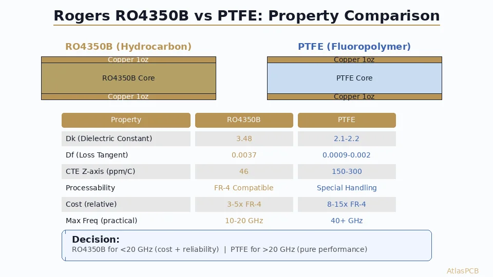
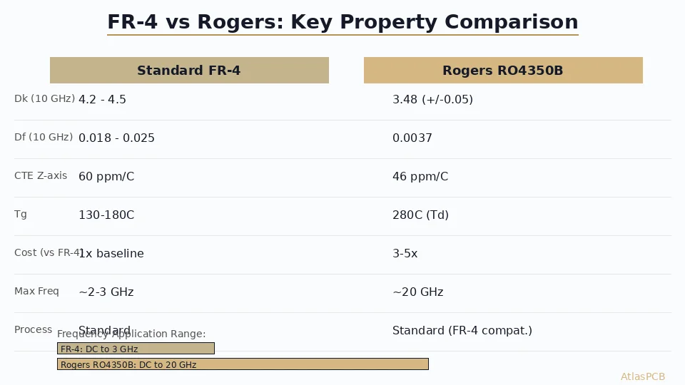
| Property | 4003C | 4350B | RT/duroid 5880 | FR4 (Standard) | Megtron 6 |
|---|---|---|---|---|---|
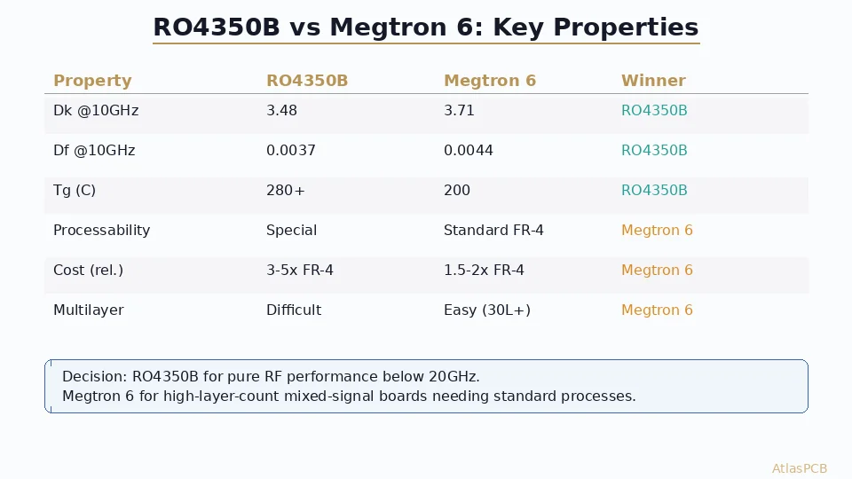
| Dk @ 10GHz | 3.38 | 3.48 | 2.20 | 4.2-4.5 | 3.71 |
| Df @ 10GHz | 0.0027 | 0.0037 | 0.0009 | 0.020-0.025 | 0.004 |
| Tg (°C) | >280 | >280 | — (PTFE) | 130-180 | 185 |
| CTE z (ppm/°C) | 46 | 32 | 237 | 50-70 | 45 |
| Moisture absorption | 0.06% | 0.06% | 0.02% | 0.10-0.15% | 0.09% |
| Processing | FR4-compatible | FR4-compatible | Special (PTFE) | Standard | FR4-compatible |
| Relative cost | 5-8x FR4 | 8-12x FR4 | 15-25x FR4 | 1x | 3-5x FR4 |
Decision framework:
- Loss-critical, budget-flexible: RT/duroid 5880
- Low loss + practical processing: Rogers 4003C ← sweet spot
- Regulatory compliance + good loss: Rogers 4350B
- Budget-sensitive, moderate frequency: Megtron 6 or low-loss FR4
- Below 1GHz, cost-driven: Standard FR4
Design Checklist for Rogers 4003C
- Confirm operating frequency requires 4003C (justify over FR4)
- Specify Dk 3.38 ±0.05 in stackup notes
- Use Rogers design Dk in field solver (not data sheet Dk)
- Select correct thickness from available options (4/6.6/8/10/12/20/32/60 mil)
- Specify copper type: ED or RA (RA for flex-to-install applications)
- Use RO4450F bondply at FR4/4003C interfaces in hybrid stackups
- Verify lamination cycle compatibility with FR4 layers
- Specify ±5% impedance tolerance in fab notes
- Add TDR coupon to test panel for impedance verification
- Confirm UL 94 rating meets regulatory requirements at your thickness
How Atlas PCB Handles Rogers 4003C
Atlas PCB maintains direct material procurement relationships with Rogers Corporation distributors, ensuring consistent lot traceability and material certification for every 4003C order.
Atlas PCB supports Rogers 4003C fabrication in all standard thicknesses (4mil to 60mil) with ±5% impedance control, hybrid FR4/Rogers stackups, and TDR verification on every controlled-impedance lot. Every order includes a 12-hour human engineering review where our RF-experienced engineers verify stackup feasibility, impedance geometry, and material interface compatibility before production begins.
For hybrid stackups, we stock Rogers 4450F bondply to ensure proper inter-layer adhesion between 4003C and FR4 sections.
Frequently Asked Questions
Is Rogers 4003C the same as 4003?
No. Rogers 4003C is the current revision with improved copper adhesion and tighter Dk tolerance (±0.05 vs ±0.08 on the original 4003). Always specify “4003C” on your fabrication drawing — not just “4003.” Manufacturers stock 4003C; original 4003 is discontinued.
What prepreg should I use with 4003C?
Use Rogers 4450F prepreg for bonding 4003C core layers together or for hybrid stackups interfacing with FR4. Rogers 4450F has Dk 3.52, which is close enough to 4003C to minimize impedance discontinuity at the core/prepreg interface. Standard FR4 prepreg (Dk 4.0-4.3) should not be placed directly adjacent to RF signal traces on 4003C.
How does 4003C perform at millimeter-wave frequencies (>30GHz)?
Rogers characterizes 4003C up to 40GHz with Df remaining below 0.0035. Multiple published antenna designs demonstrate good performance at 77GHz automotive radar frequencies. However, for the lowest possible loss at mmWave, RT/duroid 5880 (Df 0.0009) remains superior. At 77GHz, the loss difference between 4003C and 5880 becomes meaningful for multi-element phased arrays.
Summary
- Rogers 4003C delivers Dk 3.38 / Df 0.0027 at 10GHz — the lowest loss in the FR4-processable material family
- FR4-compatible processing eliminates the cost and complexity of PTFE fabrication
- Best for 2-40GHz+ applications where loss matters but PTFE handling is undesirable
- Hybrid stackups with FR4 are the standard approach — use 4003C only where you need it
- Specify 4003C, not 4003 — the original is discontinued
Need Rogers 4003C boards fabricated right? Upload your Gerbers for a free engineering review, or talk to an engineer about your RF stackup requirements.
Related guides: [Rogers 4350B vs FR4]/blog/rogers-4350b-vs-fr4/) | [RF PCB Design Guidelines]/blog/rf-pcb-design-guidelines/) | [RF PCB Materials Comparison]/blog/rf-pcb-materials-comparison/) | [PCB Material Selection Guide]/blog/pcb-material-selection-guide/)
Further Reading
[HDI PCB Design Guide: Stackup Rules, Via Structures & DFM Checklist]/blog/hdi-pcb-design-guide/)
[Microstrip vs Stripline: Routing Strategies for Controlled Impedance PCBs]/blog/microstrip-vs-stripline/)
[Multilayer PCB Stackup Design Guide: 8 to 30+ Layers Step by Step]/blog/multilayer-pcb-stackup-design-guide/)
[PCB Manufacturer with Engineering Review: Why Human DFM Audit Matters]/blog/pcb-manufacturer-engineering-review/)
[PCB Solder Mask: Types, Colors, and Functions Explained]/blog/pcb-solder-mask-guide/)
[Controlled Impedance PCB: Design, Stackup & Testing Explained]/blog/controlled-impedance-pcb/)
[PCB DFM Checklist: 50 Points to Review Before Sending Gerbers]/blog/pcb-dfm-checklist/)
[IPC Class 3 Requirements: The Complete Guide for Designers]/blog/ipc-class-3-requirements/)
[PCB Thermal Management: Heat Dissipation Techniques for Reliable Electronics]/blog/pcb-thermal-management/)
[Heavy Copper PCB: Design Rules, Manufacturing Limits, and Thermal Management]/blog/heavy-copper-pcb/)
About AtlasPCB — We specialize in complex PCB manufacturing for HDI, RF, and high-reliability applications. Explore our RF and high-frequency PCB services . Every order includes free engineering review. Get your quote.
Reviewed by AtlasPCB Engineering Team — IPC-certified manufacturing specialists with 15+ years of production experience in HDI, RF, and high-reliability PCB fabrication. Content based on factory floor data and real customer design reviews.
- Rogers 4003C
- high frequency
- RF PCB
- pcb material
- dielectric properties