Rigid-Flex PCB
Rigid Meets Flex
in One Board
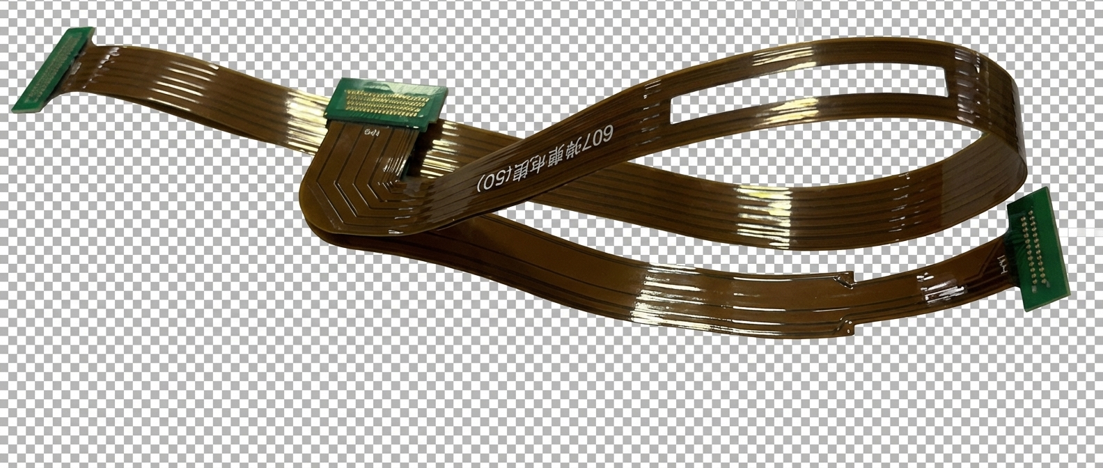
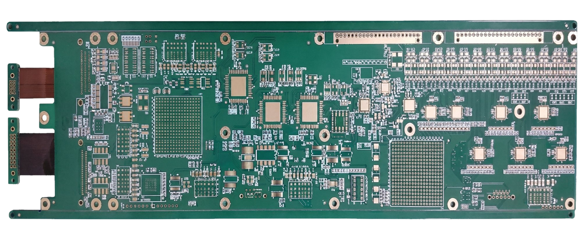
Combine rigid FR-4 sections and flexible polyimide sections in a single board. 4 to 20+ layers with 1-4 flex zones. Eliminate board-to-board connectors for military, aerospace, medical, and automotive ADAS designs.

Key Advantages
Why Choose Rigid-Flex PCBs
Rigid-flex boards solve interconnect challenges that neither rigid nor flex boards can address alone.
Eliminate Connectors and Cables
Replace board-to-board connectors and ribbon cables with integrated flex zones. One aerospace OEM removed 14 connectors from a flight computer, cutting assembly time 60% and tripling MTBF.
3D Packaging in Tight Enclosures
Fold rigid sections into compact 3D configurations. A medical implant design reduced volume by 45% by folding a 6-layer rigid-flex into a cylindrical housing.
Highest Interconnect Reliability
No solder joints between rigid sections means no connector wear-out, no contact resistance drift, and no vibration-induced intermittents. Rated for -55°C to +125°C thermal cycling.
Signal Integrity Across Boundaries
Controlled impedance traces run continuously from rigid to flex zones with no connector stubs. Critical for high-speed digital, RF, and mixed-signal designs above 1 GHz.
Technical Specifications
Rigid-Flex PCB Manufacturing Capabilities
Core Parameters
Our rigid-flex factories handle bookbinder and sculptured layup constructions, with controlled impedance across rigid-to-flex transitions.Layer Count
4-20+ total layers. Rigid sections: 2-18 layers FR-4. Flex sections: 1-4 layers polyimide.
Rigid Materials
Standard FR-4 TG150/170, high-speed (Megtron 6, Panasonic R-5775), Rogers for RF sections.
Flex Materials
Polyimide (PI) core: 12.5um-50um. Adhesiveless (2-layer) or adhesive-based (3-layer) flex constructions. Coverlay over flex zones.
Min Trace/Space
3/3mil (75um) in rigid zones, 4/4mil (100um) in flex zones. HDI microvias supported in rigid sections.
Flex Zone Bend Radius
1.5-3mm minimum (flex zones only). Static or limited-cycle dynamic bending depending on layer count and construction.
Construction and Finishes
Rigid-flex stackup design is the single most critical decision. Our engineers help you choose between bookbinder and sculptured constructions based on your bend, layer count, and cost requirements.Construction Types
Bookbinder (flex layers extend through rigid sections) and sculptured/stepped flex (flex layers terminate at rigid-flex boundary). Choice affects cost and reliability.
Transition Zone Design
Controlled radius at rigid-to-flex boundary with teardrop pads and gradual copper tapering. No vias within 1mm of transition.
Copper Weight
0.5oz-2oz in rigid zones. 0.5oz (18um) or 1oz (35um) in flex zones. Thinner copper in flex areas improves bend life.
Surface Finishes
ENIG (standard for rigid-flex), immersion silver, or OSP on rigid sections. Coverlay on flex zones. HASL not recommended due to thermal stress on flex layers.
Applications
Where Rigid-Flex PCBs Excel
Rigid-flex is the preferred solution for high-reliability, space-constrained systems where connector elimination and 3D packaging are critical.
Flight computers, guided munitions, satellite subsystems, radar modules. MIL-PRF-31032 compliant.
Pacemakers, cochlear implants, neurostimulators. Hermetic enclosure folding with biocompatible coverlays.
Camera modules, LiDAR sensor arrays, instrument cluster interconnects. AEC-Q100 thermal cycling rated.
Foldable smartphones, AR/VR headsets, professional camera systems, premium laptops.
Robotic joint interconnects, downhole drilling tools, industrial sensor arrays operating in extreme environments.
Base station RF modules, optical transceiver assemblies, high-speed backplane interconnects.
Engineering Excellence
From Prototype to Volume
Free DFM review with transition-zone and bend-radius analysis on every rigid-flex order.
Design Guidelines
DFM Best Practices for Rigid-Flex PCBs
Rigid-flex design requires mastering the transition zone between rigid and flex regions. Follow these to avoid costly redesigns.
Design the Transition Zone First
The rigid-to-flex boundary is the highest-stress area. Use gradual copper tapering, teardrop pads, and anchor spurs. No vias or components within 1mm of the transition. Define bend radius and flex length before routing.
Choose Bookbinder vs Sculptured Layup
Bookbinder: flex layers run continuously through rigid sections — simpler, lower cost, better for 1-2 flex layers. Sculptured: flex layers terminate at the boundary — more complex but allows different rigid and flex layer counts.
Maintain Impedance Across Boundaries
Dielectric thickness and copper geometry change at the rigid-flex transition. Use 2D field solvers to model impedance at the boundary. Adjust trace widths in flex zones to match rigid-zone impedance targets.
Minimize Flex Zone Complexity
Keep flex zones as simple as possible: fewer layers, thinner copper (0.5oz), no vias, no components. Route traces perpendicular to the bend axis. Use coverlay (not soldermask) over flex areas.
FAQ
Common Questions About Rigid-Flex PCBs
How much does rigid-flex cost compared to separate rigid boards with connectors?
Rigid-flex boards cost 150-400% more than an equivalent rigid board, depending on layer count and number of flex zones. However, they eliminate connector costs ($1-5 each), cable assembly labor, and reduce failure rates. For systems with 6+ board-to-board connections, total system cost often breaks even or favors rigid-flex.
What is the difference between bookbinder and sculptured (stepped) flex construction?
In bookbinder construction, the flex layers run continuously through both rigid and flex sections — simpler to manufacture and lower cost. In sculptured construction, flex layers terminate at the rigid boundary, allowing different layer counts in rigid vs flex zones. Sculptured is more expensive but necessary when rigid sections need many more layers than flex zones.
Can rigid-flex boards handle dynamic (repeated) bending?
Yes, but with limitations. Single-layer flex zones can handle 100,000+ bend cycles. Multi-layer flex zones (2-4 layers) are typically rated for static or limited-cycle bending (installation fold). For dynamic applications, minimize flex layer count and copper thickness, and increase bend radius.
What design files do I need to provide?
Provide Gerber files for all layers, a detailed stackup drawing showing rigid and flex zone layer assignments, bend zone locations with radius callouts, and a 3D model (STEP format) showing the folded configuration. Our engineers will verify the transition zones and stackup during DFM review.
Ready to Order Rigid-Flex PCBs?
Upload your Gerber files and stackup drawing for an instant quote.Free DFM review with transition-zone and bend-radius analysis included.