Rigid-Flex PCBs
Rigid-Flex Eliminate Connectors. Gain Reliability.
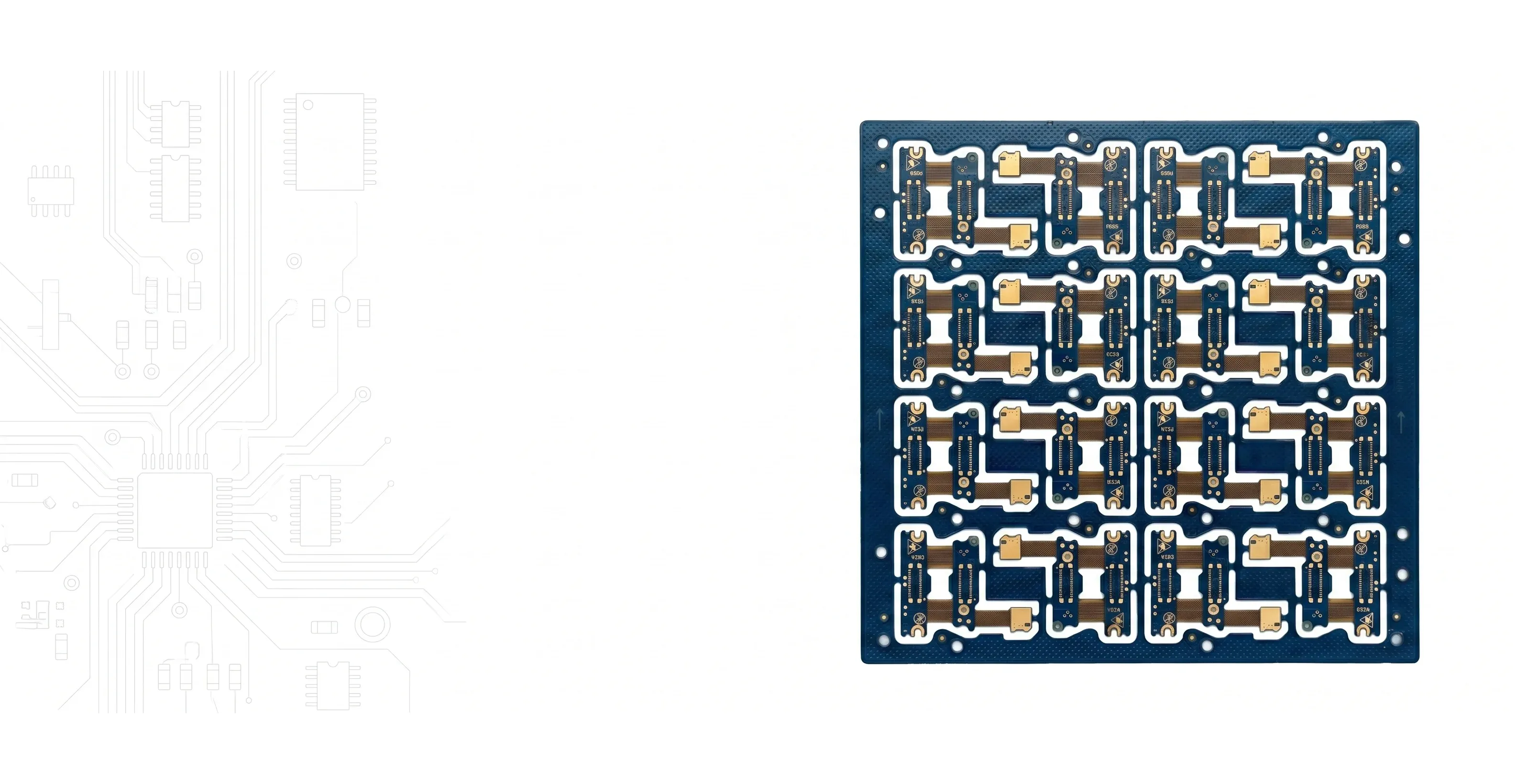
Integrated rigid and flex in one assembly. Up to 22 layers. Dynamic bend rated for 500K+ cycles. No more FPC connectors to fail.
At a Glance
The Case for Rigid-Flex
Why Integrate Instead of Connect
Every connector you eliminate is a failure point removed and assembly step saved.
Zero Connector Failures
FPC connectors are the #1 field failure point in portable electronics. Integrated flex connections have no mating cycle wear, no contact resistance drift, no latch fatigue.
3D Folding Architecture
Fold your board into the product enclosure. Rigid sections carry components, flex sections bridge between them. Dramatically reduces assembly volume.
Dynamic Motion Applications
Laptop hinges, folding phones, robotic joints, print heads. Polyimide flex rated for 500K+ bend cycles with proper design rules.
Signal Integrity Through Flex
Controlled impedance maintained through the flex zone. No connector impedance discontinuities, no stub effects, no additional signal path length.
Our Capability
Rigid-Flex Engineering Expertise
Engineered for Flex Reliability
Rigid-flex is our most engineering-intensive product. Every order receives dedicated stackup review for bend feasibility and long-term reliability.Bend Radius Verification
We calculate minimum bend radius based on your layer count, copper thickness, and flex zone width. No guessing — verified before production.
Layer Transition Design
Critical rigid-to-flex transitions engineered for stress relief. Proper anchoring, stiffener placement, and coverlay termination.
Material Selection
Polyimide substrate (25μm/50μm) with polyimide coverlay. Adhesiveless options for high-reliability. FR-4 TG170 for rigid sections.
Dynamic vs Static Optimization
Different design rules for flex that bends once (static) vs repeatedly (dynamic). Trace routing, copper annulus, and via keep-out zones all adapted.

Applications
Where Rigid-Flex Excels
Trusted in Critical Systems
When the flex zone connects life-support electronics or guides a missile, manufacturing quality isn't optional.Consumer Electronics
Smartphones, smartwatches, AR/VR headsets, folding devices, action cameras — anywhere space is measured in fractions of a millimeter.
Medical Devices
Hearing aids, pacemaker leads, endoscope tips, surgical robots. Biocompatible materials available for implantable applications.
Aerospace & Defense
Missile guidance, satellite payloads, avionics — vibration immunity and weight savings in mission-critical systems.
Industrial & Automotive
Robotic arm joints, steering column electronics, engine bay sensors — harsh environment reliability with zero connector maintenance.

FAQ
Rigid-Flex Questions
How does cost compare to separate rigid + FPC?
Per-board cost is higher. Total system cost is often lower when you factor in eliminated connectors, reduced assembly labor, smaller enclosures, and improved field reliability. ROI is strongest in volume production or high-reliability applications.
Dynamic vs static — what is the difference?
Static flex bends once during assembly and stays fixed (most common). Dynamic flex bends repeatedly in use — requires thinner PI, perpendicular trace routing, no plating in bend zone, and larger bend radius.
What is the prototype lead time?
11 days for 2-layer. Approximately 1 day per 2 additional layers. Most designs (4-8L) ship in 12-14 days.
Considering Rigid-Flex?
Upload your design or contact engineering for a stackup consultation. We'll confirm bend feasibility before you commit.
Resources
Rigid-Flex Engineering Guides
Design rules, material selection, and cost considerations for rigid-flex PCBs.
Flex and Rigid-Flex PCB Design Guidelines
Bend radius rules, conductor routing, stiffener placement, and material selection.
Dynamic Flex PCB Design: Bend Radius, Materials, and Reliability
Design rules for flex sections that bend repeatedly in use.
Flex PCB Coverlay vs Solder Mask Selection
Material selection and bend reliability comparison for flex protection layers.
Rigid vs Flexible PCB: Materials, Applications, and How to Choose
Decision framework for choosing between rigid, flex, and rigid-flex constructions.
PCB Copper Foil: ED vs RA for Flex Applications
Why rolled-annealed copper is critical for dynamic flex reliability.
Castellated Holes in PCBs: Design Rules and Module Applications
Plating requirements for board-to-board connections in modular rigid-flex assemblies.