· AtlasPCB Engineering · Engineering · 9 min read
Rogers 4350B vs FR4: When to Upgrade Your PCB Material
A head-to-head comparison of Rogers 4350B and FR4 for RF and high-speed applications. Covers Dk, Df, thermal performance, cost, and practical decision criteria for PCB engineers.
Every RF and high-speed PCB design reaches a point where the engineer asks: “Is FR4 good enough, or do I need Rogers?”
The answer depends on frequency, loss budget, impedance stability requirements, and cost sensitivity. This guide provides the data you need to make that decision — not marketing, but measured properties and practical engineering trade-offs.
Bottom Line Up Front
Use FR4 when your signals stay below 1-2GHz, loss is not a critical parameter, and cost matters more than electrical performance.
Use Rogers 4350B when your signals exceed 2-3GHz, your loss budget is tight, you need stable impedance across temperature, or you are designing antenna elements where Dk accuracy directly affects radiation pattern.
Use a hybrid stackup (Rogers for RF layers, FR4 for everything else) when your board has both RF and digital sections — which is most real-world designs.
Quick Comparison
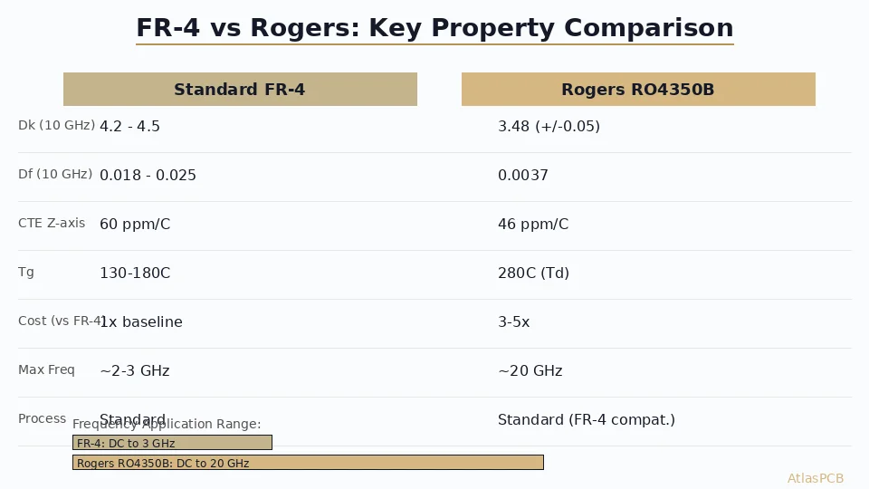
| Property | FR4 (Standard) | Rogers 4350B |
|---|---|---|
| Dk @ 10GHz | 4.2-4.5 (varies) | 3.48 ±0.05 |
| Df @ 10GHz | 0.020-0.025 | 0.0037 |
| Dk variation with frequency | ±5-10% (1MHz to 10GHz) | ±2% (1MHz to 10GHz) |
| Dk variation with temperature | ±2-3% (-40°C to +85°C) | ±0.5% (-40°C to +85°C) |
| Tg (°C) | 130-180 | >280 |
| CTE z-axis (ppm/°C) | 50-70 | 32 |
| UL 94 rating | V-0 | V-0 |
| Thermal conductivity (W/m·K) | 0.25-0.30 | 0.69 |
| Moisture absorption | 0.10-0.15% | 0.06% |
| Relative material cost | 1x | 8-12x |
| Processing compatibility | Standard | FR4-compatible (thermoset) |
What Is FR4?
FR4 is a glass-reinforced epoxy laminate — the default material for PCB manufacturing since the 1960s. “FR4” is a material family defined by NEMA grade, not a specific product, which means properties vary between suppliers.
What this means in practice:
- The Dk value in a simulation tool (typically 4.2 or 4.4) is an approximation. Actual Dk depends on resin content, glass weave style, and supplier.
- Dk varies with frequency. FR4 at 100MHz might measure 4.5; the same material at 10GHz measures 4.0-4.2.
- Dk varies with resin content. Different positions on the same panel can have different Dk if resin distribution is uneven (common with spread glass weaves).
- Df (loss tangent) increases significantly above 1GHz. Standard FR4 reaches 0.020-0.025 at 10GHz — roughly 5-7x the loss of Rogers 4350B.
For digital signals below 1GHz, these variations do not matter. A 10% impedance error on a GPIO line has no functional impact.
For RF signals, every one of these variations degrades performance.
What Is Rogers 4350B?
Rogers 4350B is a hydrocarbon ceramic-filled thermoset laminate designed for high-frequency applications. Unlike PTFE-based RF laminates (Rogers 5880, Taconic TLY-5), it uses a thermoset resin system that processes like FR4 — no special handling, no sodium etch, standard drilling and plating chemistry.
Key advantages over FR4:
- Stable Dk — 3.48 ±0.05 from 1MHz to 10GHz. This means your simulation matches your fabricated board.
- Low loss — Df 0.0037 at 10GHz, approximately 5-7x lower than standard FR4.
- Temperature stability — Dk changes less than 0.5% from -40°C to +85°C, versus 2-3% for FR4.
- Controlled Dk tolerance — Rogers specifies ±0.05, which is much tighter than the typical ±0.3-0.5 you get with FR4.
- FR4-compatible processing — No sodium etch, no plasma desmear, standard chemistry. This dramatically simplifies manufacturing and enables hybrid stackups.
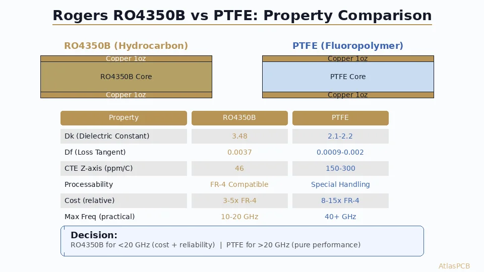
Key advantage over PTFE laminates (5880, TLY-5):
Rogers 4350B gives you most of the RF performance benefit at lower cost and much easier manufacturing. Unless you need ultra-low loss above 10GHz, 4350B is typically the better choice.
Head-to-Head: Insertion Loss
Insertion loss is the most practical metric for comparing PCB materials in RF applications. It tells you how much signal power you lose per unit length of transmission line.
For a 50Ω microstrip at various frequencies:
| Frequency | FR4 Loss (dB/inch) | Rogers 4350B Loss (dB/inch) | Difference |
|---|---|---|---|
| 1 GHz | 0.04 | 0.02 | 0.02 dB/in |
| 3 GHz | 0.12 | 0.04 | 0.08 dB/in |
| 5 GHz | 0.22 | 0.07 | 0.15 dB/in |
| 10 GHz | 0.50 | 0.15 | 0.35 dB/in |
| 20 GHz | 1.10 | 0.35 | 0.75 dB/in |
Values are approximate and depend on trace geometry, copper roughness, and specific material grade.
How to use this data: Multiply the dB/inch value by your total trace length. A 2-inch microstrip at 10GHz loses 1.0dB on FR4 versus 0.30dB on Rogers 4350B. If your receiver sensitivity requires that 0.7dB, material upgrade is mandatory — no amount of layout optimization will recover it.
At 1GHz, the difference is negligible for short traces. This is why FR4 works fine for Wi-Fi 2.4GHz on traces under 50mm.
Head-to-Head: Impedance Accuracy and Stability
Dk Predictability
Accurate impedance control requires knowing the actual Dk of your dielectric. FR4’s Dk depends on resin content, glass weave style, and frequency — three variables that are not tightly controlled.
Example: You design a 50Ω microstrip assuming Dk=4.2 on FR4. The manufacturer uses a laminate with 58% resin content (Dk≈4.0 at your frequency). Your fabricated impedance is 52Ω — outside ±5% tolerance. The board is out of spec, and the manufacturer followed their process correctly.
Rogers 4350B eliminates this problem. Dk is 3.48 ±0.05 at 10GHz. The variability is 1.4%, versus potentially 10%+ for FR4.
Temperature Stability
For applications operating over wide temperature ranges (-40°C to +85°C), Dk stability matters.
- FR4: Dk shifts 2-3% across industrial temperature range. A 50Ω trace designed at 25°C becomes 48.5-51.5Ω at temperature extremes.
- Rogers 4350B: Dk shifts <0.5%. The same 50Ω trace stays within 49.75-50.25Ω.
For narrowband filters, antenna matching networks, and coupled-line structures, this stability eliminates the need for temperature compensation in the circuit design.
Head-to-Head: Thermal Performance
| Property | FR4 | Rogers 4350B |
|---|---|---|
| Tg (°C) | 130-180 | >280 |
| Td (°C) | 300-340 | 390 |
| Thermal conductivity (W/m·K) | 0.25-0.30 | 0.69 |
| CTE z-axis (ppm/°C) | 50-70 | 32 |
Rogers 4350B conducts heat 2.3x better than FR4 and has half the z-axis thermal expansion. For power amplifier boards, transmitter modules, and other designs with significant power dissipation, this translates to lower junction temperatures and better via reliability during thermal cycling.
The Tg >280°C means Rogers 4350B is dimensionally stable through any standard soldering process, including lead-free reflow at 260°C. No risk of z-axis expansion damage during assembly.
Head-to-Head: Cost
Material cost is the most common reason engineers avoid Rogers — but the actual board cost impact is often misunderstood.
Raw material cost: Rogers 4350B costs approximately 8-12x more than standard FR4 per square foot of laminate.
Board cost impact:
| Configuration | Cost vs All-FR4 |
|---|---|
| All-Rogers 4350B (4L) | +150-200% |
| Hybrid: 2 Rogers + 2 FR4 (4L) | +40-60% |
| Hybrid: 2 Rogers + 4 FR4 (6L) | +30-50% |
| Hybrid: 2 Rogers + 6 FR4 (8L) | +25-40% |
In a 6-layer hybrid stackup where only 2 signal layers use Rogers, the material cost premium is diluted across FR4 inner layers, fabrication labor (similar to all-FR4), and test costs (same TDR process). The net board cost increase is typically 30-50% — significant, but far less than the raw material multiplier suggests.
The real cost question: Can your product tolerate FR4’s performance limitations, or will you spend more in redesigns, field failures, or compensation circuitry than the Rogers material premium?
When to Choose FR4
✅ Signal frequency is below 1-2GHz and loss is not critical
✅ Impedance tolerance of ±10% is acceptable for your application
✅ The board operates in a controlled temperature environment (no wide temperature swing)
✅ You are cost-optimizing a mature product with proven FR4 performance data
✅ Digital signals only — no RF transmission lines, antennas, or matched networks
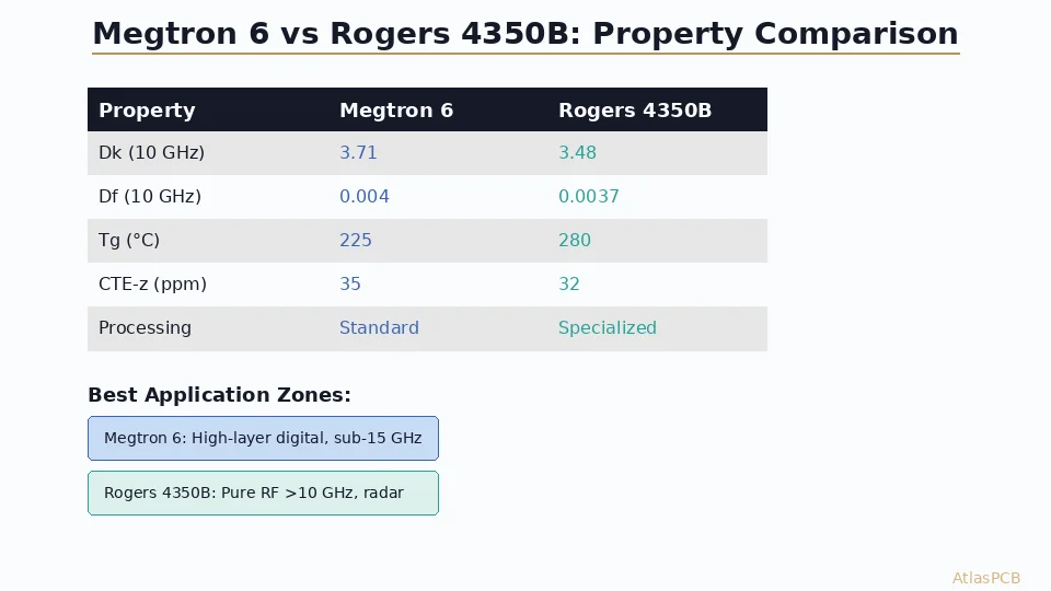
Consider low-loss FR4 variants (Megtron 4, I-Speed, Tachyon-100G) as a middle ground for high-speed digital applications at 5-25Gbps NRZ where standard FR4 loss is too high but Rogers cost is not justified.
When to Choose Rogers 4350B
✅ Signal frequency exceeds 2-3GHz and insertion loss matters
✅ Impedance accuracy of ±5% or tighter is required
✅ The design includes antenna elements where Dk accuracy affects radiation pattern
✅ Operating temperature range is wide (-40°C to +85°C) and performance must be consistent
✅ Narrowband filters or coupled-line structures depend on precise Dk
✅ Your link budget analysis shows FR4 loss is the bottleneck
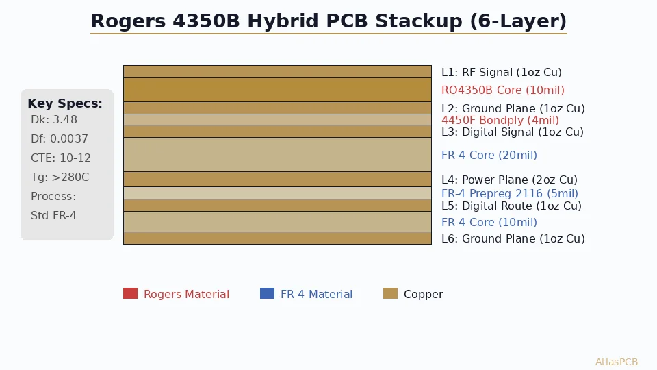
Hybrid Stackup: The Practical Answer
For most real-world designs, the answer is not “FR4 or Rogers” — it is both.
A hybrid stackup places Rogers 4350B on the layers carrying RF signals and standard FR4 on digital, power, and ground layers. This captures the RF performance benefit while minimizing material cost.
Why Rogers 4350B is ideal for hybrids:
- Thermoset resin — bonds to FR4 prepreg without special bondply (though Rogers 4450F is recommended for best results)
- CTE z-axis (32 ppm/°C) is closer to FR4 (50-70 ppm/°C) than PTFE materials (237 ppm/°C), reducing via stress at material boundaries
- Standard processing — no sodium etch, no plasma desmear, same drill and plating as FR4 layers
Hybrid stackup best practices:
- Place Rogers layers symmetrically to prevent warpage (e.g., Rogers on L1 and L6 of a 6-layer board)
- Use ground planes as buffer layers between Rogers and FR4 — this simplifies impedance modeling
- Specify Rogers 4450F bondply at the Rogers-to-FR4 interface for optimal adhesion
- Model impedance separately for Rogers and FR4 layers — do not use a single Dk value for the entire stackup
FAQ
At what frequency should I switch from FR4 to Rogers 4350B?
The transition point depends on trace length and loss budget. As a general guideline: below 1GHz, FR4 is almost always adequate. Between 1-3GHz, evaluate based on your specific loss budget — short traces may tolerate FR4 while long traces may not. Above 3GHz, Rogers 4350B or equivalent low-loss material is typically required for RF signal traces. For antenna elements where Dk accuracy matters, consider Rogers even at lower frequencies.
Can Rogers 4350B and FR4 be used in the same PCB?
Yes — hybrid stackups are common and recommended. Rogers 4350B uses thermoset resin that is compatible with FR4 processing. No special surface treatment is needed. Use Rogers 4450F bondply at the material interface, and model impedance separately for each dielectric layer. Most RF designs benefit from hybrid construction because it reduces cost without compromising RF performance.
How much more does Rogers 4350B cost compared to FR4?
The raw laminate costs 8-12x more, but total board cost increase in a typical hybrid stackup is 30-50% over all-FR4 construction. The cost premium is diluted because Rogers is only used on 1-2 signal layers in a 4-8 layer stackup, while fabrication, drilling, plating, and test costs remain similar.
Summary
- Rogers 4350B offers 5-7x lower loss and much tighter Dk control than FR4, with FR4-compatible processing
- Below 1GHz: FR4 is fine. 1-3GHz: evaluate case by case. Above 3GHz: Rogers or equivalent is typically required
- Hybrid stackups (Rogers + FR4) capture RF performance at 30-50% cost premium instead of 150-200%
- Dk at your operating frequency is what matters — not the 1MHz datasheet value
- Temperature stability, insertion loss per inch, and Dk tolerance are the three metrics that drive the material decision
Not sure if your design needs Rogers? Upload your Gerbers and our engineer will review your stackup and recommend the optimal material configuration — including hybrid options that balance performance and cost.
Related guides: [RF PCB Manufacturer]/blog/rf-pcb-manufacturer/) | [PCB Materials Guide]/blog/pcb-materials-guide/) | [PCB Impedance Control]/blog/pcb-impedance-control/)
Further Reading
[Taconic TLY-5 PCB: Properties, Applications, and Manufacturing Tips]/blog/taconic-tly-5-pcb/)
[RF PCB Materials Comparison: FR4 vs Rogers vs Taconic vs Isola]/blog/rf-pcb-materials-comparison/)
[PCB Cost Optimization: 15 Practical Ways to Reduce Board Cost]/blog/pcb-cost-optimization/)
[HDI PCB Design Guide: Stackup Rules, Via Structures & DFM Checklist]/blog/hdi-pcb-design-guide/)
[PCB Manufacturer with Engineering Review: Why Human DFM Audit Matters]/blog/pcb-manufacturer-engineering-review/)
About AtlasPCB — We specialize in complex PCB manufacturing for HDI, RF, and high-reliability applications. Explore our RF and high-frequency PCB services . Every order includes free engineering review. Get your quote.
Reviewed by AtlasPCB Engineering Team — IPC-certified manufacturing specialists with 15+ years of production experience in HDI, RF, and high-reliability PCB fabrication. Content based on factory floor data and real customer design reviews.
- Rogers 4350B
- FR4
- pcb material comparison
- high frequency
- RF design