· AtlasPCB Engineering · Engineering · 11 min read
RF PCB Manufacturer: What to Look For in a High-Frequency Board Supplier
How to evaluate RF PCB manufacturers for Rogers, Taconic, and Isola laminate boards. Covers material sourcing, impedance tolerance, mixed-dielectric capability, and supplier qualification.
RF and microwave PCBs are not just boards with different materials. They are boards where material properties directly determine electrical performance — where a 5% shift in dielectric constant changes your antenna pattern, where 0.001 increase in loss tangent adds measurable insertion loss to your signal chain, and where the wrong lamination process destroys the material properties you paid for.
Choosing the right manufacturer for RF boards is more consequential than for standard FR4, because the failure modes are subtler and the debugging is harder.
Why RF PCBs Demand a Different Manufacturer
Standard FR4 is forgiving. Its dielectric constant varies by ±5-10% from the datasheet value, loss tangent varies by frequency and resin content, and nobody notices because most digital signals below 3GHz tolerate this variation.
RF and microwave circuits do not tolerate this variation.
What makes RF PCB manufacturing different:
- Material handling — PTFE-based laminates (Rogers 5880, Taconic TLY-5) absorb moisture and require pre-bake before lamination. FR4-oriented shops may not have this process.
- Lamination parameters — RF laminates have different cure profiles than FR4. Over-pressing PTFE materials crushes the dielectric and shifts Dk.
- Drilling — PTFE materials smear during drilling, requiring plasma desmear instead of chemical desmear used for FR4.
- Plating adhesion — PTFE surfaces resist copper adhesion. Sodium etch or plasma treatment is required before plating — a process step that FR4 shops do not have.
- Impedance accuracy — At 10GHz+, a 3% Dk error translates to a 1.5% impedance error, which compounds across matched transmission lines.
A manufacturer that runs 95% FR4 may accept your Rogers 4350B order. But their process is optimized for FR4, and the RF board will inherit FR4 process assumptions that degrade performance.
RF Laminate Selection Guide
Material selection is the first design decision that determines manufacturing requirements. Here is a practical comparison of the most commonly used RF laminates.
| Property | Rogers 4003C | Rogers 4350B | Rogers 5880 | Taconic TLY-5 | Isola I-Tera MT40 |
|---|---|---|---|---|---|
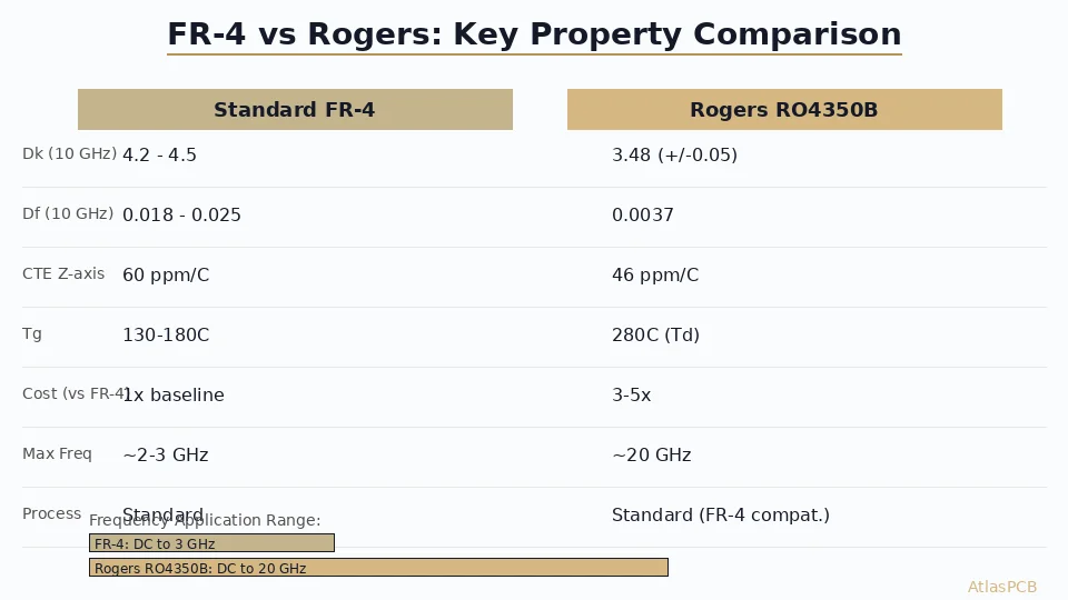
| Dk @ 10GHz | 3.38 ±0.05 | 3.48 ±0.05 | 2.20 ±0.02 | 2.20 ±0.02 | 3.45 ±0.05 |
| Df @ 10GHz | 0.0027 | 0.0037 | 0.0009 | 0.0009 | 0.0031 |
| Tg (°C) | >280 | >280 | — (PTFE) | — (PTFE) | 200 |
| CTE z-axis (ppm/°C) | 46 | 32 | 237 | 237 | 40 |
| FR4 compatible? | Yes — thermoset | Yes — thermoset | No — PTFE | No — PTFE | Yes — thermoset |
| Relative cost | 1x | 1.2x | 3-4x | 3-4x | 0.8x |
| Typical frequency | 1-10GHz | 1-10GHz | 10-77GHz | 10-77GHz | 1-15GHz |
When to Use Each Material
Rogers 4003C — The default choice for many RF designs below 10GHz. Thermoset resin (not PTFE) means it processes like FR4 — no special handling, standard chemistry, easy to combine with FR4 in hybrid stackups. Lowest cost in the Rogers family.
Rogers 4350B — Similar to 4003C but with slightly higher Dk and UL 94 V-0 flame rating (4003C is only HB-rated). Required when your design needs V-0 compliance. Slightly higher loss.
Rogers 5880 — Ultra-low loss PTFE-based laminate for demanding applications above 10GHz. Exceptional Df (0.0009) but expensive, moisture-sensitive, and difficult to process. Used in radar, satellite, and millimeter-wave designs.
Taconic TLY-5 — PTFE-based, comparable to Rogers 5880 in electrical performance. Some engineers prefer it for specific applications; sourcing and pricing vary by region.
Isola I-Tera MT40 — A high-frequency thermoset material that processes like FR4. Lower loss than standard FR4 but higher than Rogers. Good option for designs in the 1-15GHz range where Rogers cost is not justified but standard FR4 loss is too high.
7 Things to Verify in an RF PCB Manufacturer
1. Material Sourcing and Verification
The most important question: Does the manufacturer actually stock your specified laminate, or do they source it per order?
Per-order sourcing adds 1-3 weeks to lead time and introduces material substitution risk. A manufacturer who stocks Rogers 4003C, 4350B, and 5880 is signaling that RF work is a meaningful part of their business.
Ask: “Which RF laminates do you stock? What thicknesses are available off-the-shelf?” Then verify by asking for a recent material certificate (CoC) from Rogers/Taconic showing their company name as purchaser.
Red flag: If the manufacturer says “we can source any material” but cannot name specific laminate types and thicknesses in inventory, they are a broker — not a manufacturer with RF experience.
2. Mixed-Dielectric (Hybrid) Stackup Experience
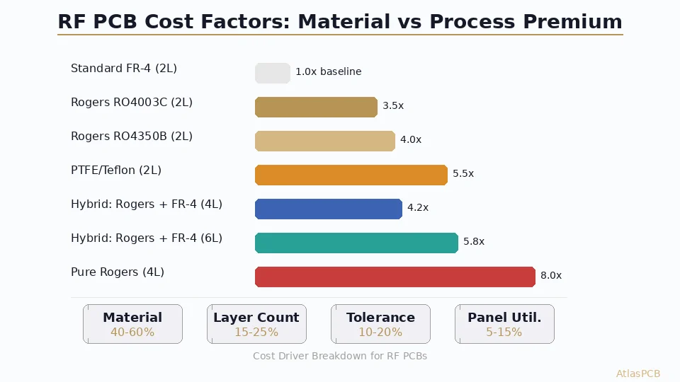
Most real-world RF designs use hybrid stackups — RF laminate on signal layers and FR4 on non-critical layers. This reduces material cost by 40-60% while maintaining RF performance where it matters.
But hybrid stackups introduce challenges:
- CTE mismatch — PTFE materials (CTE z-axis: 237 ppm/°C) expand much more than FR4 (CTE z-axis: 40-70 ppm/°C) during thermal cycling, stressing vias at material boundaries
- Bonding compatibility — Different resin systems require different prepreg bondply materials at the interface
- Lamination profile — The cure temperature and pressure must be compatible with both materials simultaneously
What good looks like: The manufacturer should propose a specific bondply material for the RF/FR4 interface, specify a lamination profile that does not exceed the RF laminate’s maximum processing temperature, and have reliability data (thermal cycling or microsection) from similar hybrid builds.
3. Impedance Control at RF Frequencies
Standard impedance control is based on Dk values at 1MHz. At RF frequencies, Dk changes — and the amount of change depends on the material.
| Material | Dk @ 1MHz | Dk @ 10GHz | Change |
|---|---|---|---|
| Standard FR4 | 4.5 | 4.2-4.4 | -2% to -7% |
| Rogers 4003C | 3.55 | 3.38 | -5% |
| Rogers 4350B | 3.66 | 3.48 | -5% |
| Rogers 5880 | 2.20 | 2.20 | <1% |
A manufacturer who calculates your impedance using Dk at 1MHz will produce a board that is 3-7% off at your operating frequency. For a 50Ω trace, that is 1.5-3.5Ω error before any manufacturing variation is added.
Verify: Ask what Dk value and frequency the manufacturer uses for impedance calculation. The answer should match your operating frequency, not “the datasheet value.”
4. PTFE Processing Capability (if applicable)
If your design uses PTFE-based laminates (Rogers 5880, RT/duroid series, Taconic TLY/RF series), the manufacturer needs specific processing capabilities:
- Pre-bake — PTFE absorbs moisture; boards must be baked at 105-120°C for 2-4 hours before lamination
- Sodium etch — PTFE surface treatment for copper adhesion. Without this, plating peels off.
- Plasma desmear — Chemical desmear used for FR4 does not work on PTFE. Plasma treatment is required after drilling.
- Modified press cycle — PTFE laminates require lower pressure and different temperature ramps than FR4
Ask: “Do you have sodium etch capability? Plasma desmear?” If the answer to either is no, they cannot reliably process PTFE-based RF materials.
Note: Thermoset RF laminates (Rogers 4003C, 4350B, Isola I-Tera) do NOT require sodium etch or plasma desmear. They process similarly to FR4, which is one of their major advantages for manufacturing.
5. Controlled Depth Routing and Cavity Milling
Many RF designs require controlled-depth features:
- Edge-plated castles for grounding RF shields
- Cavities for embedded components or antenna elements
- Stepped impedance structures with controlled dielectric removal
These features require CNC routing with depth control accuracy of ±50μm (±2 mil) — tighter than standard PCB routing. Verify the manufacturer has this capability and has used it on RF boards specifically.
6. Test Capability
RF board verification requires more than continuity testing:
- TDR testing — Verifies impedance of transmission lines and validates stackup accuracy
- Insertion loss measurement (if specified) — Requires VNA capability or test coupon design
- Visual inspection under magnification — PTFE drilling quality must be verified; smear or delamination is not always visible at standard inspection magnification
At minimum, every RF order should include TDR impedance test data on coupons fabricated alongside the production panel.
7. Engineering Support for RF Stackups
RF stackup design requires understanding of electromagnetic behavior — not just mechanical lamination. The manufacturer’s engineer should be able to:
- Recommend laminate thickness for target impedance at the specified frequency
- Calculate insertion loss per inch for the proposed transmission line geometry
- Identify via transition issues (via stub resonance, mode conversion at RF-to-FR4 boundary)
- Specify appropriate bondply for hybrid stackups
If the manufacturer’s response to your stackup question is “send us Gerbers and we’ll figure it out,” they do not have RF engineering support.
Hybrid Stackup Design: A Practical Example
A typical hybrid RF+FR4 stackup for a 2.4GHz/5GHz wireless product:
L1 — RF Signal (50Ω microstrip on Rogers 4003C)
--- Rogers 4003C 0.508mm (20mil) ---
L2 — Ground plane
--- FR4 prepreg bondply ---
L3 — Digital signal / power
--- FR4 core 0.36mm ---
L4 — Ground plane
--- FR4 prepreg bondply ---
L5 — Digital signal / power
--- Rogers 4003C 0.508mm (20mil) ---
L6 — RF Signal (50Ω microstrip on Rogers 4003C)
Key design decisions:
- Rogers 4003C for RF signal layers — thermoset resin, compatible with FR4 processing, Dk 3.38 at 10GHz
- Standard FR4 for inner digital/power layers — cost reduction on non-critical layers
- Bondply interface — Rogers 4450F or equivalent thermoplastic bondfilm between RF and FR4 layers
- Symmetrical construction — prevents warpage during reflow
Cost saving: This 6-layer hybrid costs approximately 40% less than an all-Rogers 4003C stackup while maintaining identical RF performance on the signal layers.
Common RF PCB Manufacturing Failures
| Failure | Root Cause | Impact | Prevention |
|---|---|---|---|
| Impedance out of spec | Wrong Dk used for calculation | Antenna mismatch, filter shift | Verify Dk at operating frequency |
| Insertion loss too high | PTFE damage during lamination | Reduced system gain | Controlled press pressure, verify Df post-lamination |
| Plating delamination | No sodium etch on PTFE | Board failure in field | Verify PTFE processing capability |
| Via cracking at hybrid boundary | CTE mismatch stress | Intermittent connection | Proper bondply selection, via reliability testing |
| Surface roughness variation | Inconsistent copper foil or treatment | Phase error in antenna arrays | Specify copper roughness (Rz) in fab notes |
| Material substitution | Supplier error or fraud | Complete performance failure | Require material CoC with every shipment |
How Atlas PCB Handles RF Orders
Atlas PCB maintains inventory of the most common RF laminates and partners with manufacturers whose RF production volume justifies specialized process lines.
- Stocked materials: Rogers 4003C (10/20/30/60 mil), Rogers 4350B (10/20/30/60 mil), Rogers 5880 (10/20/31/62 mil), Taconic TLY-5 (10/20/31/62 mil)
- Hybrid stackups: Proven hybrid RF+FR4 constructions with validated bondply selection
- PTFE processing: Full sodium etch, plasma desmear, and modified press cycles for PTFE-based materials
- Impedance: ±5% with TDR verification using frequency-correct Dk models
- Material traceability: Rogers/Taconic CoC provided with every shipment — verified sourcing, no substitution
- Minimum order: 1 piece — your RF prototype gets the same material and process as a production run
Every RF order includes a 12-hour human engineering pre-audit. Our CAM engineer reviews your stackup for material compatibility, impedance feasibility at your operating frequency, hybrid interface reliability, and PTFE processing requirements before production begins.
Frequently Asked Questions
What materials are used for RF PCBs?
Common RF PCB materials include Rogers 4003C (Dk 3.38, Df 0.0027 at 10GHz), Rogers 4350B (Dk 3.48, Df 0.0037), Rogers 5880 (Dk 2.20, Df 0.0009), Taconic TLY-5 (Dk 2.20, Df 0.0009), and Isola I-Tera MT40 (Dk 3.45, Df 0.0031). Material choice depends on your operating frequency, loss budget, hybrid compatibility requirements, and cost target. For most applications below 10GHz, thermoset laminates like Rogers 4003C offer the best balance of performance and manufacturability.
Can RF laminates be combined with FR4 in the same board?
Yes — hybrid or mixed-dielectric stackups are common and recommended for cost optimization. RF laminates are used on signal layers where electrical performance matters, and standard FR4 on non-critical layers (power, ground, low-frequency digital). This reduces material cost by 40-60% compared to all-RF construction. The critical requirement is proper bondply selection at the RF-to-FR4 interface and a lamination profile compatible with both materials. CTE mismatch between PTFE materials and FR4 must be managed through via design and reliability testing.
What impedance tolerance is achievable on RF PCBs?
Capable RF manufacturers achieve ±5% impedance tolerance as standard, verified by TDR testing on production coupons. Some manufacturers offer ±3% for critical applications with tighter Dk tolerance material grades. The key requirement is that impedance calculations use Dk values at your actual operating frequency — not the 1MHz value from the material datasheet. A 5% Dk error at 10GHz translates directly to a 2.5% impedance error, which is already half your tolerance budget before manufacturing variation.
Summary
- RF PCB manufacturing requires material-specific handling, lamination, and surface treatment that standard FR4 shops typically lack
- Verify material sourcing: stocked laminates signal genuine RF capability; per-order sourcing suggests occasional RF work
- Hybrid RF+FR4 stackups reduce cost 40-60% — but require proper bondply and CTE-aware via design
- Impedance calculations must use Dk at operating frequency, not 1MHz datasheet values
- PTFE-based materials (Rogers 5880, Taconic TLY-5) require sodium etch and plasma desmear — verify the manufacturer has both
- Every RF order should include TDR impedance data and material CoC
Ready to get your RF board manufactured right? Upload your Gerbers for a free engineering review, or talk to an engineer about your RF stackup and material requirements.
Related guides: [High-Frequency PCB Substrate Selection]/blog/high-frequency-pcb-substrate-selection-dk-df/) | [PCB Impedance Control]/blog/pcb-impedance-control/) | [PCB Materials Guide]/blog/pcb-materials-guide/)
Further Reading
[Impedance Controlled PCB Manufacturer: ±5% Guaranteed with TDR Testing]/blog/impedance-controlled-pcb-manufacturer/)
[Rogers 4350B vs FR4: When to Upgrade Your PCB Material]/blog/rogers-4350b-vs-fr4/)
[Rogers 4003C Material Properties: Dk, Df, and Design Considerations]/blog/rogers-4003c-properties/)
[Taconic TLY-5 PCB: Properties, Applications, and Manufacturing Tips]/blog/taconic-tly-5-pcb/)
[Multilayer PCB Stackup Design Guide: 8 to 30+ Layers Step by Step]/blog/multilayer-pcb-stackup-design-guide/)
[HDI PCB Design Guide: Stackup Rules, Via Structures & DFM Checklist]/blog/hdi-pcb-design-guide/)
[PCB Manufacturer with Engineering Review: Why Human DFM Audit Matters]/blog/pcb-manufacturer-engineering-review/)
[RF PCB Materials Comparison: FR4 vs Rogers vs Taconic vs Isola]/blog/rf-pcb-materials-comparison/)
[PCB Grounding Techniques: Star, Split, and Solid Ground Plane Strategies]/blog/pcb-grounding-techniques/)
[PCB Cost Optimization: 15 Practical Ways to Reduce Board Cost]/blog/pcb-cost-optimization/)
About AtlasPCB — We specialize in complex PCB manufacturing for HDI, RF, and high-reliability applications. Explore our RF and high-frequency PCB services . Every order includes free engineering review. Get your quote.
Reviewed by AtlasPCB Engineering Team — IPC-certified manufacturing specialists with 15+ years of production experience in HDI, RF, and high-reliability PCB fabrication. Content based on factory floor data and real customer design reviews.
- RF PCB
- high frequency
- Rogers
- Taconic
- microwave pcb
- pcb manufacturer