· AtlasPCB Engineering · Engineering · 8 min read
PCB Material Selection Guide: FR4, Rogers, Polyimide & More
A comprehensive guide to PCB material selection. Covers FR4 grades, Rogers high-frequency laminates, polyimide flex materials, thermal properties, and selection criteria by application.
Choosing the right PCB material is one of the earliest design decisions — and one of the most consequential. Material determines your board’s electrical performance, thermal behavior, mechanical properties, manufacturing complexity, and cost.
This guide covers the major PCB material families, their properties, and practical selection criteria. The goal is to help you choose the right material for your application without over-specifying (wasting money) or under-specifying (causing failures).
Material Properties That Matter
Before comparing materials, understand the properties that drive selection:
| Property | Symbol | Why It Matters |
|---|---|---|
| Dielectric constant | Dk | Determines impedance, signal speed, trace width |
| Dissipation factor | Df | Determines insertion loss (signal attenuation) |
| Glass transition temp | Tg | Maximum continuous operating temperature |
| Decomposition temp | Td | Temperature where material degrades permanently |
| CTE (z-axis) | ppm/°C | Via reliability during thermal cycling |
| Thermal conductivity | W/m·K | Heat dissipation capability |
| Moisture absorption | % | Dimensional stability, Dk stability, reliability |
| UL 94 rating | V-0/HB | Flammability classification |
FR4: The Default Material
FR4 is a glass-reinforced epoxy laminate. It is the most widely used PCB material and the default choice unless your application has specific requirements that FR4 cannot meet.
FR4 Grades
Not all FR4 is the same. The term covers a range of material grades with different properties:
| Grade | Tg (°C) | Td (°C) | Dk @1GHz | Df @1GHz | Best For |
|---|---|---|---|---|---|
| Standard Tg | 130-140 | 300 | 4.4-4.7 | 0.020-0.025 | 2-6 layer, consumer |
| Mid-Tg | 150-155 | 325 | 4.3-4.6 | 0.018-0.022 | 6-12 layer, industrial |
| High-Tg | 170-180 | 340 | 4.2-4.5 | 0.015-0.020 | 12+ layer, automotive |
| Halogen-free | 150-175 | 325-340 | 4.3-4.6 | 0.018-0.022 | Environmental compliance |
| Low-Dk/Df | 150-200 | 340-370 | 3.4-3.8 | 0.005-0.010 | High-speed digital 10Gbps+ |
Common FR4 Laminates by Name
| Laminate | Manufacturer | Tg (°C) | Dk @1GHz | Notes |
|---|---|---|---|---|
| S1000-2 | Shengyi | 170 | 4.25 | High-Tg standard, widely available |
| S1000-2M | Shengyi | 170 | 4.25 | Lead-free compatible |
| IT-180A | ITEQ | 175 | 4.30 | High-Tg, good CAF resistance |
| 370HR | Isola | 180 | 4.17 | High-Tg, halogen-free option |
| TU-872 | TUC | 175 | 4.20 | High-Tg, competitive pricing |
| Megtron 4 | Panasonic | 175 | 3.83 | Low-loss FR4 alternative |
| Megtron 6 | Panasonic | 185 | 3.71 | Very low-loss, premium |
| I-Speed | Isola | 200 | 3.63 | Low-loss, high-Tg |
| Tachyon-100G | Isola | 200 | 3.02 | Ultra-low-loss |
When FR4 Is Not Enough
FR4 hits its limits in several situations:
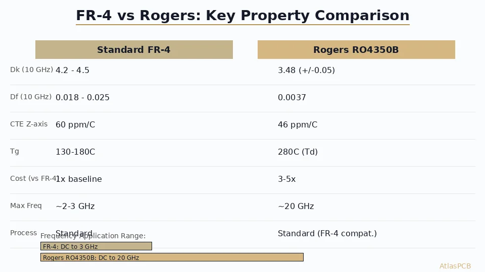
Frequency: Above 2-3GHz, FR4’s high Df causes significant insertion loss. A 50mm trace at 10GHz loses approximately 1dB more on standard FR4 than on Rogers 4350B.
Temperature: Standard Tg FR4 becomes mechanically unstable above its Tg during reflow, causing z-axis expansion that stresses via barrels. For operating temperatures above 105°C or boards with 10+ layers, use high-Tg or upgrade material.
Dk stability: FR4’s Dk varies with resin content, frequency, and temperature. For applications requiring ±2% Dk accuracy (narrowband filters, precision impedance), FR4 is too variable.
High-Frequency Materials
Rogers RO4000 Series (Thermoset)
The Rogers RO4000 series uses ceramic-filled thermoset resin — not PTFE. This is critical because thermoset materials process like FR4, making them compatible with standard manufacturing and hybrid stackups.
| Material | Dk @10GHz | Df @10GHz | Tg (°C) | CTE-z (ppm/°C) | UL 94 |
|---|---|---|---|---|---|
| RO4003C | 3.38 ±0.05 | 0.0027 | >280 | 46 | HB |
| RO4350B | 3.48 ±0.05 | 0.0037 | >280 | 32 | V-0 |
| RO4835 | 3.48 ±0.05 | 0.0040 | >280 | 32 | V-0 |
RO4003C is the go-to choice for most RF designs 1-10GHz. Lowest loss in the RO4000 family, good Dk stability, and easy to process. Limitation: HB flame rating (not V-0).
RO4350B is the most popular RF laminate overall. Slightly higher loss than 4003C but V-0 flame rated. Appropriate for any application requiring both RF performance and V-0 compliance.
For detailed comparison, see our [Rogers 4350B vs FR4 guide]/blog/rogers-4350b-vs-fr4/).
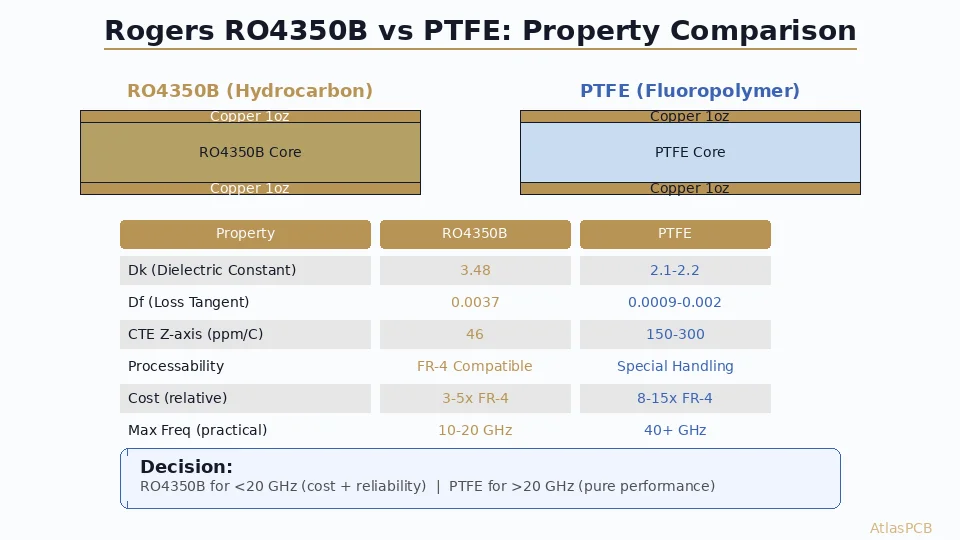
PTFE-Based Materials (High Performance)
For applications above 10GHz or ultra-low loss requirements:
| Material | Dk @10GHz | Df @10GHz | Type | Processing |
|---|---|---|---|---|
| Rogers 5880 | 2.20 ±0.02 | 0.0009 | PTFE/glass | Sodium etch required |
| Rogers 6002 | 2.94 ±0.04 | 0.0012 | PTFE ceramic | Sodium etch required |
| Taconic TLY-5 | 2.20 ±0.02 | 0.0009 | PTFE/glass | Sodium etch required |
| Taconic RF-35 | 3.50 ±0.05 | 0.0018 | PTFE ceramic | Modified processing |
PTFE materials require specialized manufacturing: sodium etch for copper adhesion, plasma desmear for via processing, controlled moisture handling, and modified lamination profiles. Not all manufacturers have this capability.
See our [RF PCB manufacturer guide]/blog/rf-pcb-manufacturer/) for details on evaluating PTFE processing capability.
Low-Loss FR4 Alternatives (High-Speed Digital)
For high-speed serial links (10Gbps+) where standard FR4 is too lossy but RF laminates are overkill:
| Material | Dk @1GHz | Df @1GHz | Processing | Cost vs FR4 |
|---|---|---|---|---|
| Megtron 4 | 3.83 | 0.005 | FR4-compatible | 2-3x |
| I-Speed | 3.63 | 0.005 | FR4-compatible | 2-3x |
| Megtron 6 | 3.71 | 0.002 | FR4-compatible | 4-6x |
| Tachyon-100G | 3.02 | 0.002 | FR4-compatible | 6-8x |
These materials process like FR4 (no sodium etch, standard chemistry) but offer 4-10x lower loss than standard FR4. They are the right choice for 25Gbps+ PAM4, 112Gbps SerDes, and similar high-speed digital applications.
Polyimide: Flexible Circuit Materials
For flexible and rigid-flex PCBs, polyimide (PI) is the standard substrate material.
| Property | Polyimide (Kapton) | FR4 |
|---|---|---|
| Dk @1GHz | 3.4-3.5 | 4.2-4.5 |
| Df @1GHz | 0.002-0.003 | 0.020-0.025 |
| Tg (°C) | >300 | 130-180 |
| Flex cycles | >100,000 (dynamic) | 0 (rigid) |
| Moisture absorption | 2.5-3.0% | 0.10-0.15% |
| Cost vs FR4 | 3-5x | 1x |
Key consideration: Polyimide absorbs significantly more moisture than FR4, which can shift Dk and cause reliability issues. Pre-bake before assembly is standard practice for polyimide flex circuits.
Metal-Core and Ceramic Substrates
For applications with extreme thermal requirements:
Metal-Core PCB (MCPCB)
Aluminum or copper base with thin dielectric layer. Used for high-power LEDs, power supplies, and motor drivers where heat dissipation is critical.
| Property | FR4 | Aluminum MCPCB | Copper MCPCB |
|---|---|---|---|
| Thermal conductivity | 0.25-0.30 W/m·K | 1.0-3.0 W/m·K | 2.0-4.0 W/m·K |
| Layers | 2-60+ | 1-2 (typically) | 1-2 |
| Cost | 1x | 1.5-3x | 3-5x |
Ceramic Substrates
Alumina (Al₂O₃) or aluminum nitride (AlN) substrates for RF power amplifiers, high-reliability hybrid circuits, and extreme temperature applications.
| Property | Alumina | AlN |
|---|---|---|
| Dk @1GHz | 9.8 | 8.9 |
| Thermal conductivity | 25-35 W/m·K | 170-230 W/m·K |
| Max temperature | >1000°C | >1000°C |
| Cost | 10-30x FR4 | 50-100x FR4 |
Ceramic substrates are outside mainstream PCB manufacturing and require specialized fabrication partners.
Material Selection Decision Tree
Step 1: What is your maximum signal frequency?
- Below 1GHz → Standard FR4 (mid-Tg or high-Tg based on layer count)
- 1-3GHz → Evaluate: short traces on FR4 may work; long traces or tight loss budget → low-loss FR4 or Rogers
- 3-10GHz → Rogers 4003C or 4350B (or hybrid with FR4)
- 10-40GHz → Rogers 5880, Taconic TLY-5, or PTFE ceramic
- 40GHz+ → Specialized PTFE or ceramic substrates
Step 2: How many layers?
- 2-6 layers → Mid-Tg FR4 minimum
- 8-16 layers → High-Tg FR4 (≥170°C) or better
- 18+ layers → High-Tg mandatory; consider lead-free reflow stress
Step 3: Any special requirements?
- Flex or rigid-flex → Polyimide
- High power dissipation → Metal-core (MCPCB)
- Extreme temperature → High-Tg FR4, polyimide, or ceramic
- Halogen-free required → Specify halogen-free grade
- V-0 flame rating required → Check material UL rating (Rogers 4003C is only HB)
Step 4: Cost sensitivity?
- Cost-critical → Standard or mid-Tg FR4 where performance allows
- Balanced → High-Tg FR4 or hybrid (RF laminate on critical layers only)
- Performance-critical → Full RF laminate or low-loss material throughout
Specifying Material on Your Fab Drawing
Do not write just “FR4” on your fabrication drawing. Specify:
- Material family — FR4, Rogers 4350B, polyimide, etc.
- Tg rating — minimum Tg (e.g., “FR4, Tg ≥170°C”)
- Specific laminate (if required) — “Shengyi S1000-2M or equivalent”
- Dk value (if impedance-controlled) — “Dk 4.2 ±0.2 at 1GHz”
- UL flame rating — V-0, HB, etc.
- Halogen-free (if required)
Example fab note: “Material: FR4, Tg ≥170°C, Dk 4.2 ±0.2 at 1GHz, UL 94 V-0. Shengyi S1000-2M, ITEQ IT-180A, or approved equivalent.”
This gives the manufacturer enough specificity to choose the right material while allowing flexibility in sourcing.
How Atlas PCB Handles Material Selection
Material selection is part of our 12-hour engineering review:
- Stocked materials: Standard FR4, mid-Tg, high-Tg (Shengyi S1000-2/2M, ITEQ IT-180A), Rogers 4003C, 4350B, 5880, Taconic TLY-5
- Sourced materials: Megtron 4/6, I-Speed, Isola 370HR, specialty polyimide — sourced per order with 1-2 week lead time
- Material verification: CoC from laminate manufacturer provided with every shipment
- Engineering review includes: Material grade verification for layer count and thermal requirements, Dk validation for impedance accuracy, and hybrid stackup material compatibility assessment
Frequently Asked Questions
What is the best PCB material for high-frequency applications?
For 1-10GHz, Rogers 4003C or 4350B offer the best balance of low loss, stable Dk, and FR4-compatible processing. For 10-77GHz, PTFE-based Rogers 5880 or Taconic TLY-5 provide ultra-low loss. For cost optimization, use hybrid stackups with RF material on signal layers and FR4 elsewhere — this saves 40-60% compared to all-RF construction while maintaining RF performance.
What does Dk and Df mean for PCB materials?
Dk (dielectric constant) controls signal propagation speed and trace impedance — lower Dk means faster signals and wider traces for the same impedance. Df (dissipation factor) controls signal loss — lower Df means less signal attenuation per unit length. Standard FR4 has Dk 4.2-4.5 and Df 0.020 at 10GHz. Rogers 4350B has Dk 3.48 and Df 0.0037 — meaning 5-7x less signal loss per unit length compared to FR4.
When should I use high-Tg FR4 instead of standard FR4?
Use high-Tg FR4 (≥170°C) for 10+ layer boards requiring sequential lamination, lead-free assembly with 245-260°C reflow, operating temperatures above 105°C, and boards undergoing multiple reflow cycles. Standard Tg FR4 (130-140°C) is adequate for simple boards in benign environments.
Summary
- Standard FR4 covers most applications below 1-2GHz — choose the right Tg grade for your layer count
- Rogers 4003C/4350B are the go-to RF materials, with FR4-compatible processing for easy hybrid stackups
- PTFE materials (Rogers 5880, Taconic TLY-5) are for demanding applications above 10GHz — require specialized manufacturing
- Low-loss FR4 alternatives (Megtron 4/6, I-Speed) bridge the gap for high-speed digital at 10Gbps+
- Always specify material completely on your fab drawing — Tg, Dk, flame rating, not just “FR4”
- Hybrid stackups reduce cost 40-60% by using premium material only where needed
Not sure which material is right for your design? Upload your Gerbers for a free engineering review — we will verify material compatibility, model impedance on the actual dielectric, and recommend the optimal material configuration.
Related guides: [Rogers 4350B vs FR4]/blog/rogers-4350b-vs-fr4/) | [RF PCB Materials Comparison]/blog/rf-pcb-materials-comparison/) | [PCB Impedance Control]/blog/pcb-impedance-control/)
Further Reading
[PCB Sequential Lamination: Process, Design Rules, and When You Need It]/blog/pcb-sequential-lamination/)
[Rogers 4003C Material Properties: Dk, Df, and Design Considerations]/blog/rogers-4003c-properties/)
[Taconic TLY-5 PCB: Properties, Applications, and Manufacturing Tips]/blog/taconic-tly-5-pcb/)
[High-Multilayer FR4 vs Standard FR4: When to Upgrade Material Grade]/blog/high-multilayer-fr4-vs-standard-fr4/)
[PCB Stackup Design: Best Practices for Signal Integrity and EMI Control]/blog/pcb-stackup-design-guide/)
[HDI PCB Design Guide: Stackup Rules, Via Structures & DFM Checklist]/blog/hdi-pcb-design-guide/)
[High-Speed PCB Design: Signal Integrity Essentials for Modern Electronics]/blog/high-speed-pcb-design/)
[Multilayer PCB Stackup Design Guide: 8 to 30+ Layers Step by Step]/blog/multilayer-pcb-stackup-design-guide/)
[PCB Manufacturer with Engineering Review: Why Human DFM Audit Matters]/blog/pcb-manufacturer-engineering-review/)
[Rigid-Flex PCB Design: Stackup, Bend Rules, and Manufacturing Guidelines]/blog/rigid-flex-pcb-design/)
About AtlasPCB — We specialize in complex PCB manufacturing for HDI, RF, and high-reliability applications. Explore our RF and high-frequency PCB services, or get an rigid-flex PCB manufacturing . Every order includes free engineering review. Get your quote.
Reviewed by AtlasPCB Engineering Team — IPC-certified manufacturing specialists with 15+ years of production experience in HDI, RF, and high-reliability PCB fabrication. Content based on factory floor data and real customer design reviews.
- pcb materials
- FR4
- Rogers
- polyimide
- laminate selection
- dielectric constant