· AtlasPCB Engineering · Engineering · 10 min read
Rigid-Flex PCB Design: Stackup, Bend Rules, and Manufacturing Guidelines
Comprehensive guide to rigid-flex PCB design covering stackup construction, bend radius calculations, dynamic flex reliability, material selection, and IPC-2223 compliance for wearables, aerospace, and medical devices.
Rigid-flex PCBs represent the most complex and rewarding construction type in PCB manufacturing. When designed correctly, they eliminate entire categories of reliability problems — every connector removed is a failure mode eliminated. When designed incorrectly, they become expensive scrap.
This guide provides the design rules and manufacturing awareness you need to get rigid-flex right on the first spin.
Why Rigid-Flex
The Connector Problem
Board-to-board connectors are the leading cause of field failures in electronics subjected to vibration, thermal cycling, or repeated mechanical stress. Every connector is a potential open circuit, every cable assembly a potential intermittent fault.
Rigid-flex eliminates these failure modes by replacing discrete connections with continuous copper:
| Connection Method | Failure Modes | Typical Field Failure Rate |
|---|---|---|
| Board + connector + cable | Contact wear, fretting corrosion, cable fatigue, solder joint crack | 0.1-1% per year per connection |
| Rigid-flex continuous | Flex fatigue (if dynamic) | 0.001-0.01% per year |
For a product with 4 board-to-board connections over a 10-year service life, rigid-flex reduces connection-related field failures by approximately 10-100×.
Space and Weight
Rigid-flex enables 3D packaging that rigid boards with cables cannot achieve:
- Thickness reduction: Eliminates connector stack height (typically 2-5mm per connection)
- Weight reduction: Polyimide flex is lighter than FR4 + connectors + cables
- Volume reduction: Flex sections fold into spaces cables cannot reach
- Repeatable geometry: Every unit folds identically, unlike hand-routed cables
Applications
- Medical devices: Implantables, endoscopes, hearing aids — where size and reliability are paramount
- Aerospace/defense: Avionics, missile guidance, satellite systems — vibration + long service life
- Consumer electronics: Smartphones, cameras, wearables — space-constrained packaging
- Automotive: Dashboard clusters, ADAS modules — vibration + temperature cycling
- Industrial: Robotics, test equipment — repeated mechanical motion
Construction Types
Type 1: Flex-to-Install (Static Flex)
The flex section bends once during assembly and remains in a fixed position for the product’s life. This is the most common and least expensive rigid-flex type.
Design freedom: Maximum. Standard materials, moderate bend radius requirements, no fatigue considerations.
Type 2: Dynamic Flex
The flex section bends repeatedly during product operation — hundreds to millions of cycles. Examples: laptop hinges, printer heads, robotic joints.
Design constraints: Severe. Requires rolled annealed copper, no plated through-holes in flex zones, careful neutral axis management, and extensive fatigue testing.
Type 3: Rigid-Flex with Bookbinder Construction
Additional rigid-only layers are added to the rigid sections through bookbinder (or blind sequential) lamination. The flex layers run continuously, and additional rigid layers are laminated on top in the rigid zones only.
This allows high layer count in rigid sections (12-24 layers) while maintaining thin, flexible flex zones (1-4 layers).
Stackup Design
Basic 4-Layer Rigid-Flex
RIGID ZONE:                    FLEX ZONE:
┌──────────────────┐           ┌──────────────┐
│ L1: Signal (FR4) │           │              │
├──────────────────┤           │              │
│ Prepreg          │           │              │
├──────────────────┤           ├──────────────┤
│ L2: GND (Poly)   │ ════════> │ L2: GND (PI) │
├──────────────────┤           ├──────────────┤
│ Polyimide Core   │ ════════> │ PI Core      │
├──────────────────┤           ├──────────────┤
│ L3: Signal (Poly)│ ════════> │ L3: Sig (PI) │
├──────────────────┤           ├──────────────┤
│ Prepreg          │           │              │
├──────────────────┤           │              │
│ L4: Signal (FR4) │           │              │
└──────────────────┘           └──────────────┘
Layers 2 and 3 are the continuous flex layers (polyimide core). Layers 1 and 4 exist only in rigid zones (FR4 + prepreg, terminated at bookbinder slots).
Key Stackup Rules
- Flex layers must be continuous — they run through both rigid and flex zones
- Flex core is polyimide — never FR4 in the flex zone
- Adhesiveless construction preferred — adhesive-based flex adds thickness and reduces reliability
- Coverlay in flex zones — polyimide coverlay replaces soldermask in flex areas
- Stiffeners optional — additional FR4 or polyimide stiffeners can be added to specific areas for component support
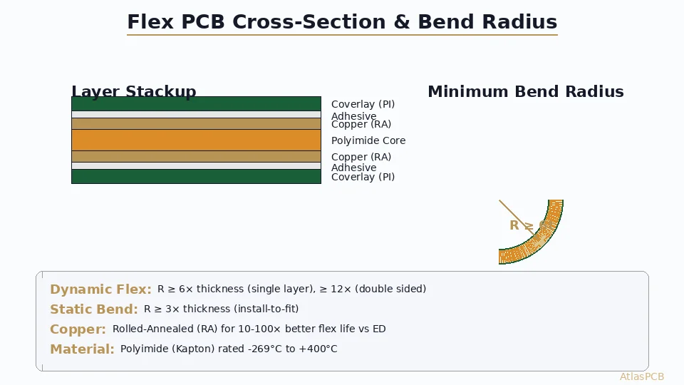
Bend Radius Rules
Static Bend (Install-and-Forget)
Minimum bend radius = 6 × total flex section thickness
| Flex Construction | Approx Thickness | Min Bend Radius |
|---|---|---|
| 1-layer (1oz Cu) | 3 mil (75µm) | 18 mil (0.46mm) |
| 2-layer (1oz Cu) | 8 mil (200µm) | 48 mil (1.2mm) |
| 4-layer (1oz Cu) | 16 mil (400µm) | 96 mil (2.4mm) |
Dynamic Bend (Repeated Flexing)
Minimum bend radius = 12 × total flex section thickness
Double the static requirement. For critical dynamic applications (>100,000 cycles), use 20× or more.
Bend Radius Measurement
Bend radius is measured to the inside surface of the bend, not the centerline. This is a common source of error — the inside surface experiences the most compression stress.
Copper in the Bend Zone
- Route traces perpendicular to the bend axis whenever possible — traces parallel to the bend axis experience maximum stress
- Stagger traces rather than stacking them directly above each other — aligned traces create stress concentration along the neutral axis
- No copper pours in bend zones — solid copper planes increase stiffness and concentrate stress. Use hatched copper (crosshatch pattern) if a ground reference is needed in the flex zone
- No plated through-holes in dynamic flex zones — the rigid plated barrel will crack under repeated bending
- Trace width: Use wider traces in bend zones (minimum 5mil, prefer 8mil+) to reduce stress per unit width

Material Selection
Flex Substrates
| Material | Dk | Df | Tg | Key Property |
|---|---|---|---|---|
| Polyimide (Kapton) | 3.4 | 0.004 | >400°C | Standard flex material |
| LCP (Liquid Crystal Polymer) | 2.9 | 0.002 | 280°C | Low loss, high frequency |
| PEN (Polyethylene Naphthalate) | 2.9 | 0.005 | 120°C | Low cost, limited temp |
Polyimide (DuPont Kapton or equivalent) is the standard for nearly all rigid-flex construction. Its combination of flexibility, thermal stability, and chemical resistance is unmatched. LCP is gaining adoption for 5G and mmWave applications where dielectric loss matters.
Copper Types
| Type | Elongation | Fatigue Life | Cost | Use Case |
|---|---|---|---|---|
| Electrodeposited (ED) | 10-15% | Good (static) | Lower | Static flex |
| Rolled Annealed (RA) | 20-30% | Excellent (dynamic) | Higher | Dynamic flex |
Rolled annealed copper is mandatory for dynamic flex applications. The grain structure of RA copper is elongated parallel to the rolling direction, providing superior fatigue resistance. ED copper has a columnar grain structure that is more prone to crack propagation under repeated bending.
Adhesive vs Adhesiveless
Traditional flex construction bonds copper to polyimide using an acrylic or epoxy adhesive layer (typically 0.5-1.0 mil thick). Adhesiveless construction deposits copper directly onto polyimide or bonds with a very thin tie coat.
Adhesiveless advantages:
- Thinner total flex section (smaller bend radius possible)
- Better thermal reliability (no adhesive degradation at high temperature)
- Better dimensional stability
- Required for HDI flex features (laser microvias)
Adhesiveless is standard for modern rigid-flex — specify it unless cost constraints require adhesive-based construction.
Transition Zone Design
The rigid-to-flex transition is the most mechanically stressed area of the entire assembly. Design failures at transitions are the leading cause of rigid-flex field failures.
Stress Concentration
At the rigid-flex boundary, the board transitions from thick and stiff (rigid FR4) to thin and flexible (polyimide). Under bending or vibration, stress concentrates at this interface like a hinge point.
Design Rules for Transitions
Taper the rigid section: Instead of an abrupt boundary, taper the rigid layers to reduce the stiffness gradient. A 30-45° taper over 50-100mil is typical.
No traces at the boundary edge: Keep copper traces at least 20mil away from the rigid-flex boundary on both sides.
No vias near the boundary: Keep plated through-holes at least 50mil from the boundary in the rigid zone. Via barrels cannot flex and will crack if too close.
Coverlay extension: Extend the polyimide coverlay at least 50mil into the rigid zone for additional reinforcement.
Anchor pads: If traces must cross the boundary, use teardrop pads at the crossing point to distribute stress.
No 90° bends at the transition: The flex zone should extend straight out from the rigid section for at least one bend radius before curving.
Design for Manufacturing (DFM)
Panelization
Rigid-flex panels are complex:
- Flex zones must be supported during processing but free to move during assembly
- Breakout tabs connect the flex to the panel frame during fabrication
- Tab placement must not interfere with bend zones
Layer Registration
Rigid-flex has inherently worse layer-to-layer registration than rigid-only boards because:
- Polyimide is dimensionally less stable than FR4
- The flex zones move during handling
- Different CTE between rigid and flex zones causes differential expansion during lamination
Plan for ±3-4mil registration tolerance in flex zones (vs ±2mil typical for rigid).
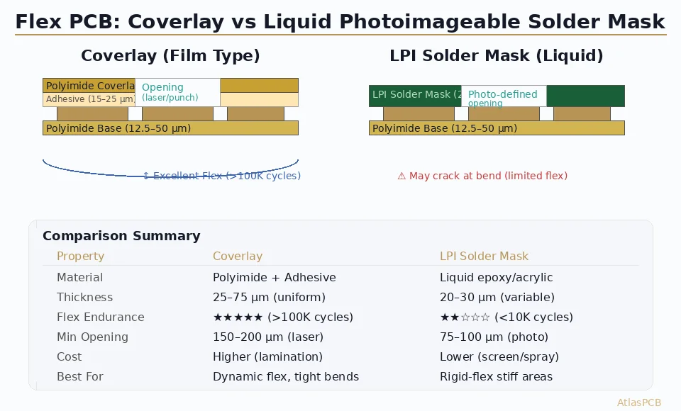
Coverlay vs Soldermask
| Feature | Coverlay (Flex Zone) | Soldermask (Rigid Zone) |
|---|---|---|
| Material | Polyimide film | Liquid photoimageable (LPI) |
| Application | Laminated (heat + pressure) | Screen printed / spray |
| Minimum opening | 8-10 mil | 3-4 mil |
| Flexibility | Excellent | Cracks when flexed |
| Registration | ±3-4 mil | ±1-2 mil |
Critical: Never apply soldermask in flex zones. It will crack during bending and delaminate, potentially causing shorts from conductive debris.
Testing and Qualification
IPC-2223 Requirements
IPC-2223 is the primary design standard for rigid-flex and flexible circuits. Key requirements include:
- Bend testing: Flex samples must survive the specified number of bend cycles at the design bend radius without opens, shorts, or resistance increase >10%
- Thermal cycling: -55°C to +125°C, 100 cycles minimum for Class 2; 500 cycles for Class 3
- Peel strength: Copper-to-polyimide adhesion minimum 4 lb/inch for Class 2, 6 lb/inch for Class 3
- Flex endurance (dynamic): MIT fold tester or IPC sliding plate method
First Article Verification
For rigid-flex designs, first article inspection should include:
- Cross-section at rigid-flex transitions — verify layer alignment, adhesion, taper geometry
- Bend test — verify design bend radius is achievable without damage
- Impedance verification — test both rigid and flex zone impedance
- Thermal cycling — minimum 100 cycles to verify transition zone integrity
At Atlas PCB, our engineering pre-audit includes DFM review of all rigid-flex transition zones, bend radius verification, and material compatibility checks before production begins.
Common Design Mistakes
Mistake 1: Copper Pours in Flex Zones
Large copper areas significantly increase flex zone stiffness and concentrate bending stress. If a ground reference is needed, use hatched (crosshatch) copper with 50% or less fill — this provides adequate electrical shielding while maintaining flexibility.
Mistake 2: Symmetric Stackup in Flex Zones
A symmetric flex stackup (equal copper and dielectric on both sides of the neutral axis) is ideal for stress distribution, but many designs inadvertently create asymmetric flex sections. Asymmetric construction means one surface experiences more strain than the other during bending, leading to premature fatigue failure.
Mistake 3: Components Too Close to Bend Zones
Components, pads, and vias placed near the rigid-flex boundary or in the flex zone create rigid islands that act as stress risers. Maintain a clear keep-out zone of at least 100mil from any component pad to the start of the flex bend zone.
Mistake 4: Ignoring Flex Zone Thickness in Z-Height Budget
The flex section, even when folded flat, adds thickness. A 4-layer flex section is approximately 16mil thick — multiply by the number of folds and factor into your enclosure Z-height budget.
Frequently Asked Questions
How many layers can the flex zone support?
Practically, 1-4 layers for dynamic flex and 1-6 layers for static flex. Each additional layer increases flex thickness, which increases minimum bend radius and reduces fatigue life. Most dynamic flex designs use 2 layers (signal + ground). Static flex can use up to 6 layers for complex routing, but 4 layers is a practical limit for reasonable bend radii. The rigid sections can have any number of layers — 20+ layer rigid sections with 2-layer flex zones are common in aerospace applications.
Can I use HDI features (microvias, laser drills) in rigid-flex?
Yes, but only in the rigid sections. Microvias and sequential lamination processes are standard in rigid zones. In flex zones, only through-holes (for static flex) or no holes (for dynamic flex) are permitted. The boundary between HDI-capable rigid zones and flex zones must be clearly defined in the stackup documentation.
What is the typical lead time for rigid-flex PCBs?
Rigid-flex lead times are typically 3-5 weeks for prototypes and 4-8 weeks for production — roughly 2× longer than equivalent rigid boards. The extended time reflects the additional manufacturing steps: separate flex circuit fabrication, coverlay lamination, rigid-flex lamination, and the specialized inspection required at each stage. Rush options are available but significantly more expensive due to the sequential nature of rigid-flex processing.
Further Reading
[HDI PCB Design Guide: Stackup Rules, Via Structures & DFM Checklist]/blog/hdi-pcb-design-guide/)
[HDI PCB Technology: Microvias, Laser Drilling, and High-Density Design]/blog/hdi-pcb-technology/)
[PCB Sequential Lamination: Process, Design Rules, and When You Need It]/blog/pcb-sequential-lamination/)
[Multilayer PCB Stackup Design Guide: 8 to 30+ Layers Step by Step]/blog/multilayer-pcb-stackup-design-guide/)
[PCB DFM Checklist: 50 Points to Review Before Sending Gerbers]/blog/pcb-dfm-checklist/)
[IPC Class 3 Requirements: The Complete Guide for Designers]/blog/ipc-class-3-requirements/)
About AtlasPCB — We specialize in complex PCB manufacturing for HDI, RF, and high-reliability applications. Explore our rigid-flex PCB manufacturing, or get an full PCB manufacturing capabilities . Every order includes free engineering review. Get your quote.
Reviewed by AtlasPCB Engineering Team — IPC-certified manufacturing specialists with 15+ years of production experience in HDI, RF, and high-reliability PCB fabrication. Content based on factory floor data and real customer design reviews.
- rigid-flex
- flex PCB
- pcb design
- polyimide
- IPC-2223
- wearable electronics