· AtlasPCB Engineering · News · 7 min read
DDR5 Memory PCB Design Challenges: 4800 MT/s Signal Integrity Requirements Push PCB Capabilities
DDR5 memory's leap to 4800 MT/s and beyond demands new PCB design strategies for signal integrity, trace routing, and material selection. Here's what designers need to know.
DDR5 Changes the Game for PCB Design
The widespread adoption of DDR5 memory in servers, workstations, and high-end consumer platforms has introduced a new generation of PCB design challenges that are pushing the boundaries of conventional manufacturing capabilities. With base data rates starting at 4800 MT/s and the JEDEC roadmap extending to 8800 MT/s and beyond, the signal integrity demands placed on printed circuit boards have never been more exacting.
Unlike its predecessor DDR4, which operated at a maximum of 3200 MT/s, DDR5 introduces fundamental architectural changes — including on-die error correction code (ECC), a dual 32-bit channel architecture replacing the single 64-bit channel, and decision feedback equalization (DFE) — that collectively reshape how PCB designers must approach memory subsystem layout.
The Signal Integrity Challenge at 4800+ MT/s
At 4800 MT/s, DDR5 signals operate with a unit interval (UI) of approximately 208 picoseconds. This leaves extraordinarily tight timing margins where even minor impedance discontinuities, via stubs, or trace length mismatches can cause bit errors. As data rates climb to 5600 MT/s, 6400 MT/s, and the recently ratified 7200 MT/s specification, these margins shrink further.
Key signal integrity challenges include:
Crosstalk management. At DDR5 frequencies, near-end and far-end crosstalk between adjacent signal traces become critical failure modes. The recommended trace-to-trace spacing has increased to a minimum of 3× the trace width for DDR5 data lines, compared to 2× for DDR4. Designers must also account for aggressor-victim coupling across multiple layers, requiring careful stackup planning.
Impedance control. DDR5 specifies single-ended impedance targets of 40Ω for data signals (DQ/DQS), tighter than DDR4’s 40–60Ω range. Achieving consistent 40Ω impedance across the entire signal path — from DIMM connector through PCB traces to the memory controller BGA — demands precise [controlled impedance]/blog/controlled-impedance-pcb/) fabrication with tolerances of ±7% or better.
Insertion loss budgets. The total channel insertion loss budget for DDR5 at 4800 MT/s is approximately 6 dB at the Nyquist frequency (2.4 GHz). At 6400 MT/s, this budget tightens to roughly 5 dB at 3.2 GHz. These stringent loss budgets directly impact permissible trace lengths, via counts, and connector transitions.
Trace Length Matching: Tighter Than Ever
DDR5’s dual-channel architecture, while improving bandwidth efficiency, doubles the number of byte lanes that must be precisely length-matched. Each 32-bit sub-channel requires independent length matching of its DQ, DQS, DM/DBI, and address/command signals.
The JEDEC specification calls for intra-byte-lane skew of <2 ps for DQ-to-DQS matching, which translates to approximately 0.3 mm of trace length difference at typical propagation velocities on FR-4. For designers working with [high-speed PCB layouts]/blog/high-speed-pcb-design/), this represents a significant tightening from DDR4’s <5 ps allowance.
Address and command signals, now operating at higher frequencies due to DDR5’s increased command bus speed, require their own length matching with tolerances of ±25 mils (0.635 mm) within each group.
Material Selection Becomes Critical
Standard FR-4 laminates, which served adequately for DDR4 designs, are increasingly marginal for DDR5 at speeds above 5600 MT/s. The dielectric loss (Df) of standard FR-4 at 0.020–0.025 creates excessive insertion loss in longer memory channel traces.
Designers targeting DDR5-6400 and above are moving toward mid-loss and low-loss materials:
- Mid-loss laminates (Df 0.010–0.015): Suitable for DDR5-5600 to DDR5-6400 with moderate trace lengths
- Low-loss laminates (Df <0.010): Required for DDR5-7200+ or designs with longer channel lengths
- Ultra-low-loss materials (Df <0.005): Used in server platforms where maximum memory bandwidth and longest trace lengths are required
Selecting the right [PCB material]/blog/pcb-material-selection-guide/) is no longer optional — it is a first-order design decision that directly impacts whether a DDR5 interface will meet its performance targets.
Stackup Design Considerations
DDR5 PCB stackups require careful attention to reference plane continuity and layer assignment. Best practices emerging from the industry include:
Dedicated ground reference planes. Every DDR5 signal layer should be immediately adjacent to a continuous ground plane. Split planes or shared power/ground references that were tolerable at DDR4 speeds can create return-path discontinuities that degrade signal quality at DDR5 data rates.
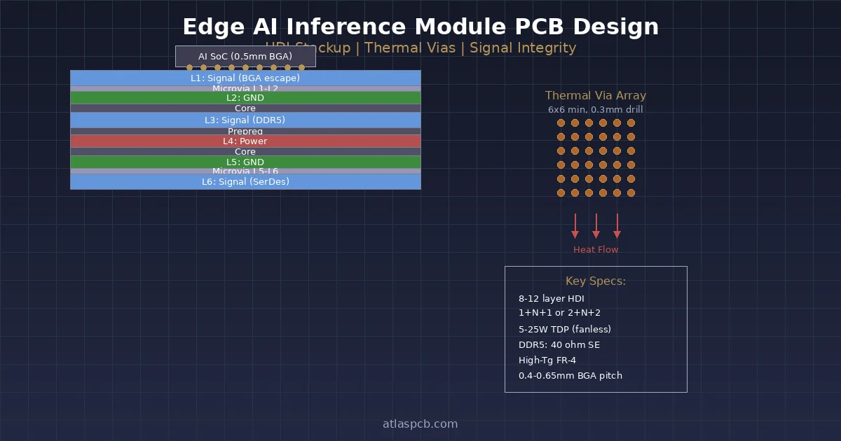
Controlled dielectric thickness. To achieve the 40Ω single-ended target with practical trace widths (typically 3.5–5 mils), dielectric thicknesses of 3.0–4.5 mils between signal and reference layers are common. This requires [HDI-class]/blog/hdi-pcb-design-guide/) fabrication capabilities for many designs.
Via optimization. Through-hole vias create stubs that act as resonant antennas at DDR5 frequencies. For boards thicker than 1.6 mm, back-drilling is recommended to reduce via stubs to <10 mils. In advanced designs, blind and buried microvias eliminate stubs entirely.
Layer count increases. A typical DDR5 server motherboard now requires 12–16 layers minimum, compared to 8–12 for equivalent DDR4 designs, driven by the additional routing channels and ground reference requirements.
On-Die ECC: Implications for PCB Designers
DDR5’s on-die ECC corrects single-bit errors within each DRAM chip before data reaches the memory bus. While this feature improves memory reliability, it has subtle implications for PCB design.
On-die ECC operates transparently — it does not change the external bus width or signal count. However, it can mask marginal signal integrity that would have caused visible errors in DDR4 systems. This creates a risk: a DDR5 design that appears to function correctly may be operating with unacceptably high pre-ECC bit error rates, reducing the effective ECC correction margin available for soft errors from radiation or aging.
PCB designers should target raw bit error rates well below the on-die ECC correction threshold, meaning signal integrity margins must be designed conservatively rather than relying on ECC as a safety net.
Power Delivery Challenges
DDR5 shifts the voltage regulator from the motherboard to the DIMM module itself (PMIC — Power Management IC), which simplifies motherboard power delivery. However, the 1.1V VDD operating voltage (down from DDR4’s 1.2V) means tighter noise margins on the power distribution network (PDN).
The motherboard must still deliver 12V to the DIMM connector for the on-module PMIC, and the quality of decoupling on the motherboard’s 12V rail affects DIMM power quality. Additionally, VPP (2.5V) is still supplied from the motherboard and requires clean, low-impedance delivery.
Effective [thermal management]/blog/pcb-thermal-management/) around the memory subsystem is also increasingly important as DDR5 modules consume 20–30% more power than DDR4 equivalents due to higher data rates.
Manufacturing Tolerances Tighten
The cumulative effect of DDR5’s design requirements is a significant tightening of manufacturing tolerances:
| Parameter | DDR4 Typical | DDR5 Required |
|---|---|---|
| Impedance tolerance | ±10% | ±7% |
| Trace width tolerance | ±0.5 mil | ±0.3 mil |
| Dielectric thickness | ±10% | ±7% |
| Registration accuracy | ±3 mil | ±2 mil |
| Via drill accuracy | ±2 mil | ±1 mil |
These tolerances push DDR5 motherboard fabrication into [IPC Class 3]/blog/ipc-class-3-requirements/) territory for many parameters, requiring PCB manufacturers with advanced process control capabilities.
Industry Response and Outlook
Major server OEMs including Dell, HPE, and Lenovo have reported yield learning curves of 6–12 months when transitioning motherboard designs from DDR4 to DDR5, primarily driven by signal integrity optimization iterations. EDA vendors including Cadence, Synopsys (Ansys), and Keysight have released DDR5-specific simulation templates and channel compliance checking tools.
The PCB industry is responding with investments in advanced impedance testing, time-domain reflectometry (TDR) capabilities, and tighter process controls. Fabricators that can consistently meet DDR5 requirements are positioning themselves for the growing market, which Yole Group estimates will exceed $35 billion in DDR5 DRAM revenue by 2027.
As DDR5 speeds continue to climb toward the 8800 MT/s ceiling and DDR6 development begins, the symbiotic relationship between memory technology and [PCB manufacturing capability]/blog/pcb-manufacturing-process-15-steps/) will only deepen.
What This Means for PCB Buyers
Organizations designing DDR5-based platforms should engage their PCB manufacturing partners early in the design cycle. Key considerations include:
- Specify material requirements upfront — standard FR-4 may not suffice above 5600 MT/s
- Plan for additional design iterations — DDR5 signal integrity optimization typically requires 2–3 board spins
- Budget for advanced testing — TDR, insertion loss testing, and impedance verification add cost but prevent costly failures
- Select manufacturers with proven high-speed capabilities — DDR5 exposes process weaknesses that DDR4 designs could tolerate
Atlas PCB works with designers tackling DDR5 and other high-speed memory interface challenges, providing the tight-tolerance fabrication and advanced materials handling these designs demand.
Atlas PCB provides high-speed PCB fabrication with controlled impedance and advanced material support for DDR5 and next-generation memory designs. Request a quote for your next project.
About AtlasPCB — We specialize in complex PCB manufacturing for HDI, RF, and high-reliability applications. Explore our impedance-controlled PCB manufacturing . Every order includes free engineering review. Get your quote.
Reviewed by AtlasPCB Engineering Team — IPC-certified manufacturing specialists with 15+ years of production experience in HDI, RF, and high-reliability PCB fabrication. Content based on factory floor data and real customer design reviews.
- news
- ddr5
- signal-integrity
- high-speed
- memory-pcb