· AtlasPCB Engineering · Engineering · 9 min read
Rogers 4350B Stackup Design Guide: Hybrid Layer Configuration for 5G and Radar Applications
Complete Rogers 4350B stackup design guide covering hybrid FR-4/Rogers configurations, impedance targeting for 5G front-ends, and manufacturing constraints for 4-12 layer RF boards.
Quick Answer
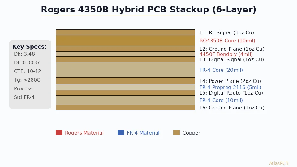
For 5G and radar PCB applications, a hybrid Rogers 4350B stackup places the low-loss laminate (Dk=3.48, Df=0.0037) on the outer layers where RF traces route, while using standard FR-4 for the inner core to reduce cost by 35-50% compared to an all-Rogers build — achieving insertion loss below 0.5 dB/inch at 28 GHz on properly designed microstrip.
Quick Reference: Rogers 4350B Stackup Parameters
| Parameter | Value | Notes |
|---|---|---|
| Dk (process) | 3.48 +/-0.05 | At 10 GHz, design Dk |
| Df (loss tangent) | 0.0037 | At 10 GHz |
| Z-axis CTE | 32 ppm/C | vs FR-4 at 60 ppm/C |
| Available thicknesses | 4, 6.6, 10, 13.3, 16.6, 20, 30, 60 mil | Standard Rogers stock |
| Copper options | ED (standard), RA (low-profile) | RA recommended for mmWave |
| Tg | >280C | Thermoset, no true glass transition |
| Moisture absorption | 0.06% | Negligible impact on Dk stability |
| Processing | FR-4 compatible | Standard oxide/epoxy bonding works |
The critical advantage of Rogers 4350B over PTFE-based alternatives (like RT/duroid 5880) is manufacturability. 4350B processes on standard FR-4 equipment with standard bonding methods — no special plasma treatment or sodium etch required. This makes hybrid stackups practical in any facility that handles multilayer FR-4.
Hybrid Stackup Architecture: Why Not All-Rogers?
The engineering rationale for hybrid Rogers/FR-4 stackups is straightforward: only your RF traces need the low-loss dielectric. Power distribution networks, digital control signals, and ground planes work perfectly on FR-4. Placing Rogers 4350B exclusively where RF signals propagate — typically the outer two layers in a surface-mount microstrip topology — delivers 90% of the RF performance at 40-50% less cost than an all-Rogers build.
From a mechanical perspective, pure Rogers stackups present challenges that hybrid construction solves elegantly. Rogers 4350B is stiffer and more brittle than FR-4, making all-Rogers boards susceptible to mechanical shock damage during assembly and handling. An FR-4 core provides structural compliance and allows standard mounting hardware without risk of cracking the laminate near screw holes.
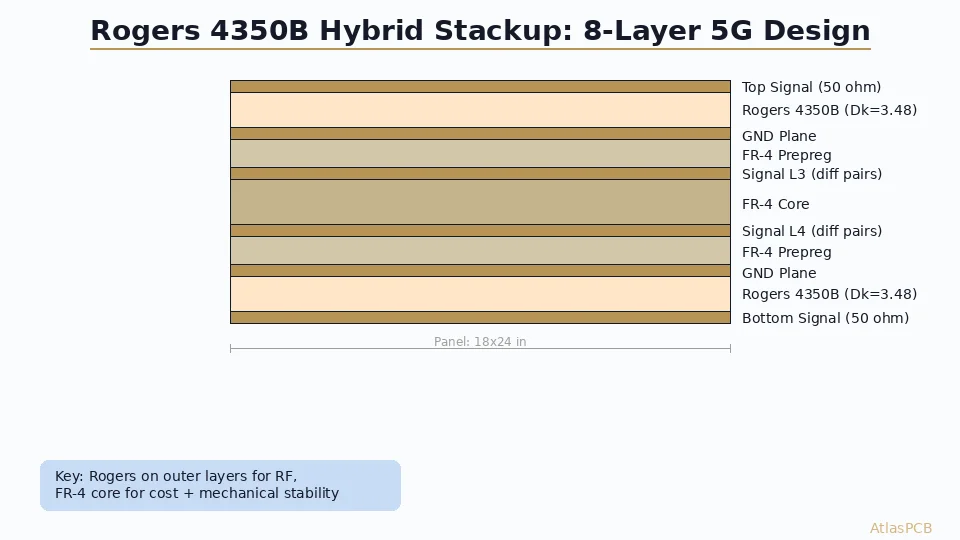
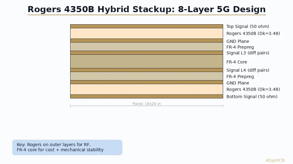
In our production experience across several hundred Rogers hybrid builds per month, the optimal configuration for most 5G applications is what we call the “RF sandwich” — Rogers 4350B on the outermost signal layers (typically L1/L2 and L7/L8 in an 8-layer design), with standard high-Tg FR-4 forming the structural core. This gives your RF engineer low-loss microstrip on the surfaces where antenna feeds, PA outputs, and LNA inputs route, while the digital and power sections buried in the FR-4 core handle everything else.
ROGERS PCB MANUFACTURING
Custom Rogers 4350B Hybrid Stackups
Send us your RF requirements. We design the optimal hybrid stackup with impedance simulation and material sourcing included.
Request Stackup Design ›
Stackup Examples: 4-Layer Through 12-Layer
4-Layer Configuration (Sub-6 GHz)
For Wi-Fi 6E, Bluetooth, and sub-6 GHz cellular designs where two RF layers suffice:
| Layer | Material | Thickness | Purpose |
|---|---|---|---|
| L1 (Top) | Rogers 4350B | 10 mil (0.254mm) | RF microstrip |
| Bond film | Rogers 4450F | 4 mil | Bonding layer |
| L2 | Copper | 1 oz | Ground plane (RF reference) |
| Core | FR-4 (Tg170) | 40 mil | Structural |
| L3 | Copper | 1 oz | Power/ground |
| Bond film | FR-4 prepreg | 8 mil | Standard bonding |
| L4 (Bottom) | Rogers 4350B | 10 mil | RF microstrip / digital |
This configuration achieves 50-ohm microstrip at 12.5 mil trace width on the Rogers layers, with approximately 0.35 dB/inch insertion loss at 6 GHz. Total board thickness lands around 62 mil (1.57mm), compatible with standard connectors and enclosures.
8-Layer Configuration (28 GHz mmWave)
The workhorse stackup for 5G NR FR2 applications, phased array feeds, and automotive radar IF:
| Layer | Material | Thickness | Purpose |
|---|---|---|---|
| L1 | Rogers 4350B | 6.6 mil | Antenna elements / RF |
| L2 | Copper (GND) | 0.5 oz | Immediate RF ground reference |
| Prepreg | Rogers 4450F | 4 mil | Low-loss bond |
| L3 | Copper (Signal) | 0.5 oz | Digital control / beamformer |
| Core | FR-4 | 20 mil | Structural core |
| L4 | Copper (Power) | 1 oz | Power distribution |
| Prepreg | FR-4 | 6 mil | Standard |
| L5 | Copper (GND) | 1 oz | Power plane reference |
| Core | FR-4 | 20 mil | Structural core |
| L6 | Copper (Signal) | 0.5 oz | Digital / low-speed |
| Prepreg | Rogers 4450F | 4 mil | Low-loss bond |
| L7 | Copper (GND) | 0.5 oz | Bottom RF ground |
| L8 | Rogers 4350B | 6.6 mil | Bottom RF / calibration |
At 28 GHz, the 6.6 mil Rogers 4350B delivers approximately 0.8 dB/inch for a 50-ohm microstrip — acceptable for trace lengths under 1 inch typical in phased array feed networks. The thin dielectric (6.6 mil vs 10 mil) narrows the microstrip trace to approximately 9 mil, which requires 3/3 mil manufacturing capability for the associated differential pairs and spacing.
Manufacturing Constraints We See Most Often
Based on our production data from hundreds of Rogers hybrid builds:
Registration accuracy becomes critical at 6.6 mil dielectric — a 1 mil misregistration between L1 copper and L2 ground shifts impedance by approximately 2 ohms. Our process holds +/-2 mil layer-to-layer registration, adequate for sub-6 GHz but tight for 28 GHz designs where every ohm counts.
Drill-to-copper clearance near RF traces requires attention. Plated through-holes create impedance discontinuities proportional to their proximity to controlled-impedance traces. We recommend minimum 20 mil clearance from any via barrel to controlled trace edge on Rogers layers.
Panel utilization drops significantly with Rogers hybrids because Rogers sheet sizes (18x12 or 18x24 inch) constrain panelization differently than FR-4 (which comes in 18x24 or 24x36). Designing your board outline to maximize Rogers sheet utilization can save 10-15% on material cost.
RF PCB ENGINEERING
Need Help with Your Rogers Stackup?
Our RF process engineers review your design requirements and recommend the optimal Rogers/FR-4 hybrid configuration with impedance targets.
RF PCB Services ›Impedance Targeting on Rogers 4350B
The design Dk for Rogers 4350B is 3.48 at 10 GHz (process specification, not the 3.66 you see on older datasheets measured at 1 MHz). This matters enormously for impedance calculations — using the wrong Dk value produces a trace width that is off by 5-8%, which translates directly to impedance error.
For microstrip on 10 mil (0.254mm) Rogers 4350B with 1 oz (35um) copper:
- 50 ohm single-ended: 12.5 mil trace width (0.318mm)
- 100 ohm differential: 8 mil trace, 7 mil gap (0.203mm / 0.178mm gap)
- 75 ohm single-ended: 7.5 mil trace width (0.191mm)
For embedded stripline on 10 mil Rogers 4350B with 0.5 oz copper:
- 50 ohm single-ended: 6.5 mil trace width (requires tight etch control)
- 100 ohm differential: 5 mil trace, 5 mil gap (at the edge of most capabilities)
Our process engineers typically recommend microstrip over stripline for Rogers layers because microstrip on a thin, well-controlled dielectric achieves excellent impedance accuracy without the manufacturing complexity of burying traces between two Rogers dielectric layers. The outer-layer microstrip also allows impedance trimming through controlled etch-back if needed — a recovery option unavailable for buried traces.
The frequency-dependent Dk shift in Rogers 4350B is minimal but worth accounting for in wideband designs. Between 1 GHz and 40 GHz, the effective Dk drops from approximately 3.52 to 3.44 — a 2.3% variation. For narrowband applications (typical 5G NR channels at 100-400 MHz bandwidth), this shift is negligible. For ultra-wideband designs spanning multiple octaves, use the Dk at your center frequency for impedance calculations.
CTE Mismatch Management in Hybrid Builds
The one manufacturing concern that keeps PCB process engineers awake at night with hybrid Rogers/FR-4 stackups is z-axis CTE (Coefficient of Thermal Expansion) mismatch. Rogers 4350B expands at 32 ppm/C in the z-axis, while standard FR-4 expands at approximately 60 ppm/C below Tg and 200-300 ppm/C above Tg. During the 180-190C lamination cycle and subsequent reflow soldering at 250C peak, these differential expansion rates create stress at the material interfaces.
In our facility, we manage this through three proven approaches:
First, we use a controlled lamination profile with extended dwell time (40-60 minutes at peak temperature versus the 30 minutes typical for all-FR-4). The slower thermal ramp rate (1.5-2.0C/minute versus 3.0C/minute) allows gradual stress relaxation at the Rogers/prepreg interface, preventing microcracking.
Second, we specify Rogers 4450F or Arlon 45NK as the bonding prepreg between Rogers and FR-4 layers. These thermosetting bond films have intermediate CTE values (40-45 ppm/C) that act as a stress buffer. Using standard FR-4 prepreg directly against Rogers laminate creates a sharp CTE discontinuity that increases delamination risk during thermal cycling.
Third, we limit the total Rogers dielectric thickness relative to the FR-4 core. Our empirical rule is that Rogers layers should not exceed 30% of total stackup thickness in any hybrid build. An 8-layer board at 62 mil total with Rogers 4350B at 6.6 mil on top and bottom (13.2 mil total Rogers = 21% of stackup) is well within our comfort zone. A design trying to use 20 mil Rogers on all four signal layers (80 mil Rogers in a 100 mil stackup) would require careful reliability qualification.
CHINA RF PCB MANUFACTURER
Rogers 4350B In Stock. 8-12 Day Lead Time.
We maintain Rogers 4350B inventory in 4, 6.6, 10, and 20 mil thicknesses. No minimum order quantity for hybrid builds.
Get RF PCB Quote ›DFM Considerations for Rogers Stackup Designs
Before sending your Rogers 4350B design to fabrication, verify these manufacturing-critical parameters:
Drill considerations: Mechanical drilling through Rogers material produces less smear than FR-4 due to the thermoset ceramic-filled resin system, but drill bit life is reduced by approximately 30% due to abrasive ceramic fillers. For laser-drilled microvias on Rogers layers, our CO2 laser process requires adjusted energy parameters — Rogers absorbs laser energy differently than FR-4, requiring 20-30% higher fluence to achieve clean via formation. Specify your microvia requirements upfront so we can plan the appropriate laser recipe.
Copper bonding: Rogers 4350B requires an oxide treatment (brown oxide or alternative) for reliable copper-to-laminate adhesion. Standard FR-4 inner-layer bonding processes work, but the peel strength specification is critical — we test to ensure >6 lb/inch peel strength on all Rogers interfaces, versus the >4 lb/inch typical for FR-4.
Panelization: Rogers material waste is expensive ($150-250 per standard sheet depending on thickness). Discuss your board dimensions with us before finalizing the design — a 2mm adjustment in board outline can sometimes fit one more board per Rogers sheet, saving $8-12 per piece on a 100-unit run.
ATLASPCB
Start Your Rogers 4350B Project
Upload your stackup specification or Gerbers. We provide impedance modeling, material recommendation, and quoted pricing — typically within 24 hours.
Upload Design ›
Reviewed by AtlasPCB Engineering Team — 15+ years in advanced PCB fabrication for RF, HDI, and rigid-flex applications.
Related Reading:
About AtlasPCB — We specialize in complex PCB manufacturing for HDI, RF, and high-reliability applications. Explore our RF and high-frequency PCB services, Rogers RO4350B PCB manufacturing, or get an multilayer PCB fabrication up to 30 layers . Every order includes free engineering review. Get your quote.
Reviewed by AtlasPCB Engineering Team — IPC-certified manufacturing specialists with 15+ years of production experience in HDI, RF, and high-reliability PCB fabrication. Content based on factory floor data and real customer design reviews.
Frequently Asked Questions
What is the optimal Rogers 4350B stackup for 5G applications?
Can Rogers 4350B be combined with FR-4 in the same stackup?
What impedance can I achieve with Rogers 4350B at 0.254mm thickness?
How much does a Rogers 4350B hybrid stackup cost compared to all-FR-4?
- rogers-pcb
- stackup-design
- rf-pcb
- 5g-manufacturing