· AtlasPCB Engineering · Engineering · 10 min read
Rogers 4350B vs PTFE for RF PCB: Material Selection Guide for 5-77 GHz Designs
In-depth comparison of Rogers RO4350B and PTFE (RT/duroid 5880) for RF PCB applications. Covers dielectric loss, CTE compatibility, fabrication complexity, cost, and hybrid stackup strategies. Helps RF engineers decide which material to specify for their frequency range and volume requirements.
Quick Answer
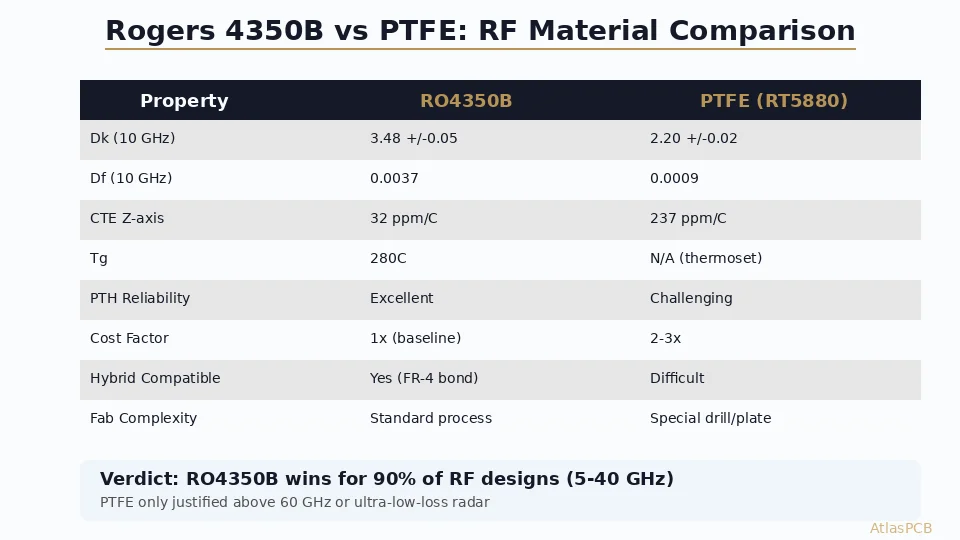
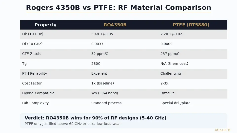
Rogers RO4350B is the right choice for 90% of RF PCB applications between 5-40 GHz due to its excellent PTH reliability, FR-4-compatible processing, hybrid stackup capability, and acceptable loss tangent of 0.0037 at 10 GHz. PTFE materials like RT/duroid 5880 (Df = 0.0009) are only justified above 60 GHz, for ultra-low-loss radar front-ends, or when insertion loss budget leaves zero margin — and they require specialized fabrication processes that add 2-3x cost.
Quick Answer: RO4350B for 90% of RF Designs, PTFE Only Above 60 GHz
| Parameter | Rogers RO4350B | PTFE (RT5880) | Winner |
|---|---|---|---|
| Dk at 10 GHz | 3.48 +/-0.05 | 2.20 +/-0.02 | PTFE (lower = faster propagation) |
| Df at 10 GHz | 0.0037 | 0.0009 | PTFE (4x lower loss) |
| CTE-Z (ppm/C) | 32 | 237 | RO4350B (PTH reliable) |
| Tg / Td | 280C / 390C | N/A (no Tg) | RO4350B |
| PTH Reliability | Excellent (>6x reflow) | Poor (max 3x reflow) | RO4350B |
| Hybrid FR-4 Bond | Standard lamination | Requires special adhesive | RO4350B |
| Drill/Plate | Standard process | Sodium etch + controlled drill | RO4350B |
| Cost Multiplier | 2-3x FR-4 | 5-8x FR-4 | RO4350B |
| Best Frequency Range | 1-40 GHz | 40-110 GHz | Depends on application |
The decision is straightforward for most RF engineers: if your operating frequency is below 40 GHz and your insertion loss budget can tolerate 0.003-0.004 dB/mm at 10 GHz, Rogers RO4350B delivers 95% of PTFE’s performance at 40% of the cost and fabrication complexity. PTFE becomes necessary only when you’re pushing millimeter-wave frequencies above 60 GHz, building long-distance radar receivers where every 0.1 dB matters, or working in radio astronomy applications with extreme noise figure requirements.
The Engineering Case for RO4350B
The fundamental advantage of Rogers RO4350B is not its RF performance — it’s that it achieves genuinely good RF performance while remaining compatible with standard PCB fabrication infrastructure. This compatibility is not a minor detail. It determines whether your board can be manufactured by hundreds of qualified fabs worldwide or only by a dozen specialists.
RO4350B uses a thermoset ceramic-filled hydrocarbon resin system. Unlike PTFE, which is essentially a fluoropolymer (Teflon) with glass or ceramic filler, the RO4350B chemistry cross-links during lamination and forms a rigid, dimensionally stable structure. The practical consequence is a CTE-Z of 32 ppm/C — close enough to copper’s 17 ppm/C that plated-through-hole barrels survive repeated thermal cycling without cracking. In our production line, we routinely process RO4350B boards through 6+ lead-free reflow cycles (peak 260C) with zero barrel failures on standard 0.3mm drill PTH vias.
The thermoset chemistry also means RO4350B can be drilled with standard tungsten carbide bits at normal feed rates. There is no smearing, no gumming of the bit, and no requirement for specialized entry/exit materials. We use the same drill parameters we use for high-Tg FR-4 (Isola 370HR): 180K RPM spindle speed, 60 ipm infeed for 0.3mm bits, with standard aluminum entry material. The boards come off the drill with clean hole walls that plate uniformly without additional surface preparation.
For the RF engineer, this translates to faster lead times, lower costs, and more vendor options. A 4-layer RO4350B/FR-4 hybrid ships in 7-10 days from our facility — the same as a standard FR-4 multilayer. An equivalent PTFE board requires 12-18 days due to the additional surface preparation steps.
RF PCB MATERIALS
Need a Rogers 4350B Quote?
We fabricate hybrid Rogers/FR-4 and all-Rogers stackups with impedance control to +/-5%. Standard 7-10 day lead time for RF boards.
Upload Gerber Files ›
When PTFE Actually Makes Sense
PTFE materials (RT/duroid 5880, RT/duroid 5870, Taconic TLY-5) occupy a specific niche: applications where dielectric loss is the dominant system constraint and no other design parameter can be relaxed to compensate.
The loss tangent advantage is substantial — 0.0009 versus 0.0037 at 10 GHz, a factor of 4x. But this 4x advantage translates to real-world insertion loss differences that are smaller than most engineers expect. On a 50-ohm microstrip line at 10 GHz, RO4350B exhibits approximately 0.17 dB/cm of total loss (dielectric + conductor), while RT5880 achieves approximately 0.08 dB/cm. For a typical 5 cm signal path on an RF front-end, that’s 0.85 dB versus 0.40 dB — a 0.45 dB difference.
Whether that 0.45 dB matters depends entirely on your link budget. In most 5G sub-6 GHz designs, WiFi modules, and Bluetooth applications, the system has 3-10 dB of margin beyond what’s needed. Spending 3x the board cost to recover 0.45 dB is poor engineering economics. But in a 77 GHz automotive radar receiver where the noise figure target is 4.5 dB and the entire receive chain is budgeted to the tenth of a dB, that 0.45 dB can be the difference between meeting and missing specification.
The frequency-dependent loss scaling is the other factor. Dielectric loss increases roughly linearly with frequency, while conductor loss scales with the square root of frequency. At 77 GHz, the dielectric loss of RO4350B reaches approximately 0.5 dB/cm for microstrip, making PTFE’s 0.12 dB/cm a more compelling advantage — particularly for distributed filter structures or antenna feed networks with long transmission line segments.
From a manufacturing perspective, PTFE’s challenges are real but manageable for an experienced RF PCB manufacturer. The sodium naphthalenide etch (or plasma treatment) required for copper adhesion adds 4-6 hours of process time and a chemical handling step. The soft material requires reduced drill feed rates (40% slower than FR-4), more frequent bit changes (every 500 hits versus 3000 for FR-4), and careful control of backup material to prevent exit burrs. In our facility, we process approximately 200 PTFE panels per month with a first-pass yield of 92% — lower than our 97% yield on RO4350B, but acceptable for the premium these customers are already paying.
CHINA RF PCB MANUFACTURER
Both Rogers and PTFE — One Qualified Source
AtlasPCB maintains active material agreements with Rogers, Taconic, and Isola. Our process engineers help you choose the right material for your frequency and budget.
Hybrid Stackup: The Best of Both Worlds
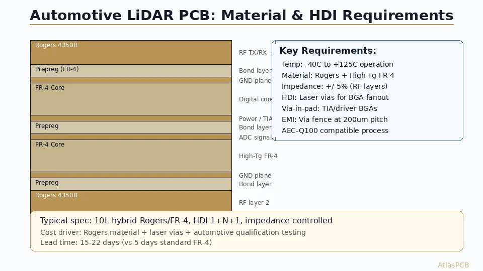
The most cost-effective approach for the majority of RF designs is a hybrid stackup that uses Rogers material only where RF performance is critical — typically the antenna layer and any high-frequency transmission line layer — while using standard FR-4 for digital, power, and low-frequency signal routing.
A typical 6-layer hybrid for a 5G NR sub-6 GHz radio module:
| Layer | Material | Thickness | Purpose |
|---|---|---|---|
| L1 | RO4350B | 10 mil | Antenna patches + RF feed |
| Bond | RO4450F prepreg | 4 mil | Rogers-compatible bond ply |
| L2 | Copper | 1 oz | Ground plane (RF reference) |
| Core | FR-4 (370HR) | 12 mil | Structural + digital routing |
| L3 | Copper | 1 oz | Digital signals / power |
| Prepreg | FR-4 prepreg | 4 mil | Standard bond |
| L4 | Copper | 1 oz | Digital signals |
| Core | FR-4 (370HR) | 12 mil | Structural |
| L5 | Copper | 1 oz | Ground plane |
| Bond | Standard prepreg | 4 mil | — |
| L6 | FR-4 | — | Power / low-speed I/O |
The critical design decision in hybrid stackups is the bonding interface between Rogers and FR-4 layers. RO4350B bonds cleanly with RO4450F prepreg (a Rogers bond ply specifically designed for this purpose) or with standard high-Tg FR-4 prepreg if the lamination profile is adjusted. In our facility, we’ve validated both approaches and found that RO4450F provides more consistent peel strength (7-9 lb/in versus 5-7 lb/in for standard prepreg bond), but either passes IPC-TM-650 peel testing requirements.
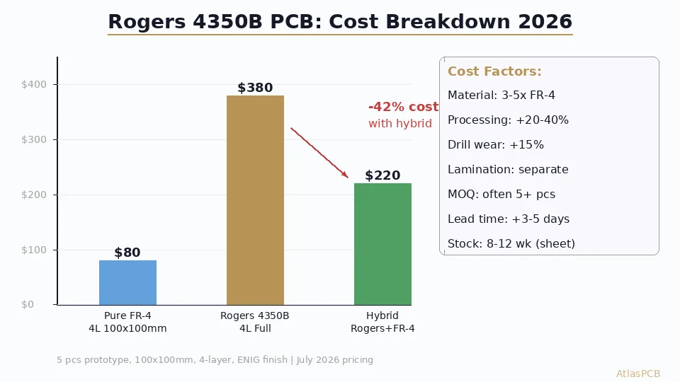
The cost savings are significant. A 6-layer all-Rogers RO4350B board runs approximately 4x the cost of standard FR-4. The hybrid approach described above typically comes in at 1.8-2.2x — saving 50% of the Rogers premium while maintaining full RF performance on the critical layers. For a production run of 500 boards (100x80mm), that’s the difference between $32,000 and $18,000 for bare boards alone.
Fabrication Reliability: Where RO4350B Dominates
The most overlooked advantage of RO4350B is long-term reliability — specifically, what happens to your PCB after 5 years of thermal cycling in the field. This is where the CTE-Z difference between 32 ppm/C (RO4350B) and 237 ppm/C (PTFE) becomes a product liability concern rather than an academic comparison.
Every time a PTFE-based PCB heats up — whether from a power-on cycle, an ambient temperature change, or a reflow during rework — the substrate expands in the Z-axis by 7.4x more than RO4350B. The copper barrel in a plated-through-hole via is constrained to expand at copper’s CTE (17 ppm/C). This CTE mismatch between the substrate and the barrel creates shear stress at the barrel-to-pad interface that accumulates with each thermal cycle.
For PTFE boards, we recommend limiting via aspect ratios to 6:1 and specifying minimum 25 um copper plating thickness in PTH barrels. Even with these precautions, PTFE boards should not be specified for applications requiring more than 3 lead-free reflow cycles. We’ve seen barrel cracking failures in PTFE boards after the 4th reflow at 260C peak in our reliability testing — failures that simply do not occur in RO4350B construction even at 8+ cycles.
This reliability difference makes RO4350B the clear choice for any RF product that requires rework capability (prototype and low-volume production), operates in wide temperature ranges (automotive, outdoor infrastructure), or must survive multiple assembly processes (SMT top, SMT bottom, selective wave, hand solder rework). PTFE should be reserved for applications where the assembly is straightforward (single reflow, no rework expected) and the operating temperature range is moderate.
ENGINEERING REVIEW
Not Sure Which RF Material to Specify?
Our RF process engineers review your design files and recommend the optimal material for your frequency, loss budget, and volume. No charge for the consultation with a production order.
Get Recommendation ›Decision Framework: Choosing Your RF Substrate
The material choice should follow your operating frequency and loss budget, not the marketing preferences of material suppliers. Here is the framework our process engineers use when advising customers:
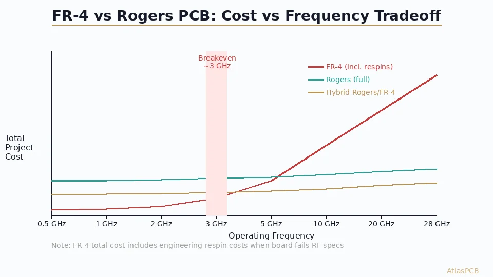
Below 6 GHz (WiFi, BLE, sub-6 GHz 5G NR, GPS): Standard high-Tg FR-4 (Isola 370HR, Dk 4.04, Df 0.009 at 1 GHz) is often sufficient. The loss tangent contribution over typical trace lengths (10-30mm) adds less than 0.3 dB — well within most link budgets. If your design is marginal, move to RO4350B on the RF layer only.
6-40 GHz (5G mmWave, automotive radar feed, Ka-band satcom): RO4350B is the sweet spot. Its Df of 0.0037 keeps insertion loss manageable even on 10-15 cm feed network runs, while its fabrication compatibility keeps costs reasonable and lead times short. Hybrid stackups with FR-4 cores are standard practice.
40-77 GHz (77 GHz radar antenna, V-band backhaul): This is the transition zone. Short signal paths (antenna patches, direct feed stubs under 10mm) can still use RO4350B or the lower-loss RO3003. Longer transmission lines or distributed filter structures benefit from PTFE. Many automotive radar modules use RO3003 (Df 0.0013) as a compromise — better loss than RO4350B, better processability than pure PTFE.
Above 77 GHz (W-band, D-band, radar imaging): PTFE-based materials (RT5880, RT5870) or liquid crystal polymer (LCP) become necessary. At these frequencies, even modest dielectric loss compounds rapidly over wavelength-scale structures.
ATLASPCB
Ready to Order Your RF Board?
Upload your Gerber files and stackup. We'll confirm material availability, verify impedance targets, and quote within 4 hours for Rogers and PTFE constructions.
Get Instant Quote ›
Reviewed by AtlasPCB Engineering Team — 15+ years in advanced PCB fabrication for RF, HDI, and rigid-flex applications.
Related Reading:
About AtlasPCB — We specialize in complex PCB manufacturing for HDI, RF, and high-reliability applications. Explore our RF and high-frequency PCB services, Rogers RO4350B PCB manufacturing, or get an multilayer PCB fabrication up to 30 layers . Every order includes free engineering review. Get your quote.
Reviewed by AtlasPCB Engineering Team — IPC-certified manufacturing specialists with 15+ years of production experience in HDI, RF, and high-reliability PCB fabrication. Content based on factory floor data and real customer design reviews.
Frequently Asked Questions
Is Rogers 4350B better than PTFE for RF PCB?
Can Rogers 4350B be used for 77 GHz automotive radar?
Why is PTFE harder to fabricate than Rogers 4350B?
What is a hybrid Rogers/FR-4 PCB stackup?
How much does Rogers 4350B PCB cost compared to standard FR-4?
- FR-4 vs Rogers PCB
- Rogers 4350B stackup
- Rogers PCB manufacturer
- RF PCB design and manufacturing