· AtlasPCB Engineering · News · 8 min read
IPC Study Reveals New Insights on Lead-Free Solder Joint Reliability Under Thermal Cycling
A comprehensive IPC research program delivers critical findings on SAC305 solder joint performance under extended thermal cycling, with major implications for automotive and aerospace PCB assemblies.
Landmark Research Challenges Assumptions About Lead-Free Solder Longevity
The IPC — Association Connecting Electronics Industries — has released the complete findings from its three-year comprehensive study on lead-free solder joint reliability under extended thermal cycling conditions. Published as IPC-9701C Supplement A, the research delivers what industry experts are calling the most significant update to lead-free solder reliability data since the original RoHS transition era, with findings that could reshape how engineers approach [reliability testing]/blog/pcb-reliability-testing/) for long-life electronic assemblies.
The study, conducted across six independent laboratories with participation from 23 industry partners, examined the behavior of SAC305 (Sn96.5/Ag3.0/Cu0.5) solder joints — the most widely used lead-free alloy in electronics manufacturing — under thermal cycling conditions ranging from the mild (0°C to +100°C) to the extreme (-55°C to +125°C). What the researchers found challenges several long-held assumptions about solder fatigue behavior and has immediate implications for automotive, aerospace, and industrial electronics applications.
The Critical Finding: Accelerated Fatigue Beyond 3,000 Cycles
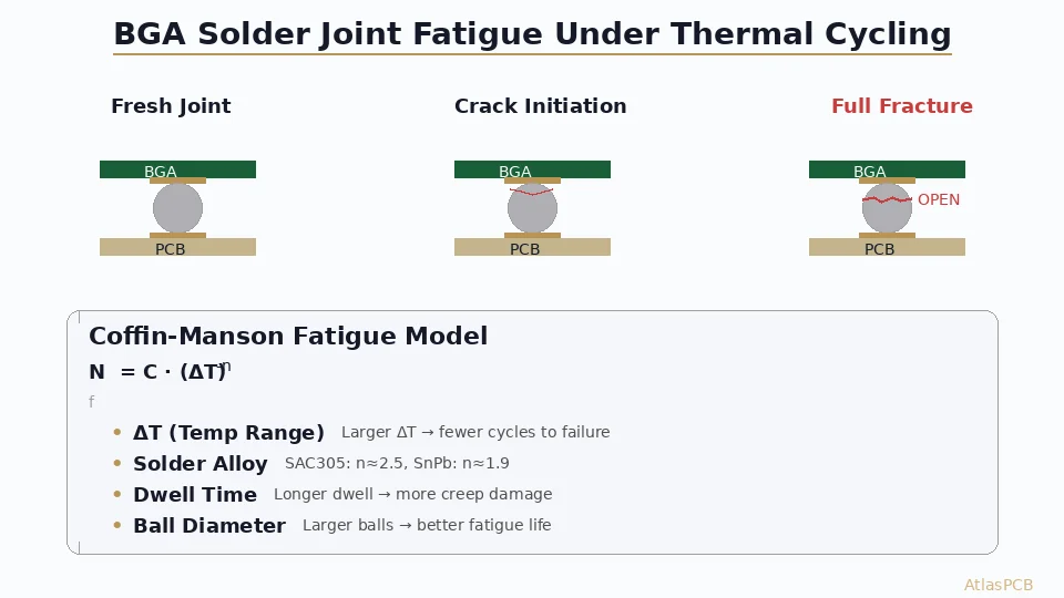
The study’s headline finding centers on a previously undocumented fatigue acceleration mechanism in SAC305 solder joints. Under the automotive-grade thermal cycling profile (-40°C to +125°C, 60-minute cycles with 15-minute dwell times), SAC305 joints exhibited predictable Coffin-Manson fatigue behavior up to approximately 3,000 cycles. Beyond this threshold, however, crack propagation rates increased by 35% to 50%, driven by a grain boundary coarsening phenomenon that current reliability prediction models do not account for.
“What we observed is a distinct transition in the failure mechanism,” explained Dr. Ranjit Pandher, the study’s principal investigator. “Below 3,000 cycles, fatigue cracks propagate through the expected intergranular pathways. Above 3,000 cycles, the Ag3Sn intermetallic particles that normally pin grain boundaries have coarsened to the point where they no longer provide effective crack arrest. The result is a significant acceleration in fatigue damage accumulation.”
For context, 3,000 cycles under the -40°C to +125°C profile represents roughly 7 to 10 years of service life for an underhood automotive ECU, depending on duty cycle and geographic location. This means that PCB assemblies designed for the industry-standard 15-year automotive service life may be operating in the accelerated fatigue regime for a significant portion of their intended lifespan.
Deep Dive into the Metallurgical Findings
Grain Structure Evolution
The research team used scanning electron microscopy (SEM) and electron backscatter diffraction (EBSD) to document the evolution of SAC305 grain structure throughout the thermal cycling process. At the beginning of life, SAC305 joints exhibit a fine-grained structure with Ag3Sn intermetallic particles distributed along grain boundaries, acting as barriers to crack propagation.
Through thermal cycling, the cyclic strain causes progressive recrystallization and grain growth. The study documented a clear three-phase evolution:
- Phase 1 (0–1,500 cycles): Minimal grain coarsening, crack initiation at stress concentration points
- Phase 2 (1,500–3,000 cycles): Moderate grain growth, Ag3Sn particles begin to coarsen, crack propagation follows established Coffin-Manson relationships
- Phase 3 (3,000+ cycles): Rapid grain boundary coarsening, Ag3Sn particles agglomerate, crack propagation accelerates beyond model predictions
Package-Specific Results
The study examined multiple package types, recognizing that solder joint geometry significantly influences fatigue behavior. Results varied markedly across package formats:
BGA packages (0.8mm and 1.0mm pitch): These showed the strongest accelerated fatigue effect, with crack propagation rates increasing by up to 50% after 3,000 cycles. The combination of larger solder ball volume and the constraint provided by the component substrate creates conditions that promote grain coarsening.
QFN packages: Showed a 35% acceleration in crack propagation, with the bottom-terminated pad geometry creating stress concentrations that interact with the grain coarsening mechanism.
Chip components (0402, 0603, 0805): Exhibited the least sensitivity to the accelerated fatigue mechanism, likely due to the smaller solder volume and simpler joint geometry. However, even these smaller joints showed measurable acceleration at extreme thermal cycling conditions.
Through-hole components: Were not significantly affected, as the barrel-fill solder joint geometry provides more uniform stress distribution and greater solder volume to accommodate crack growth.
Implications for Industry Standards and Practices
Impact on IPC-Class 3 Requirements
The findings have immediate relevance for electronics assemblies built to [IPC Class 3 requirements]/blog/ipc-class-3-requirements/), which are specified for high-reliability applications including military, aerospace, medical, and automotive systems. The current [IPC-Class 2 versus Class 3 distinction]/blog/ipc-class-2-vs-class-3/) focuses primarily on manufacturing workmanship standards, but the study suggests that reliability prediction methods used to qualify Class 3 assemblies may need updating.
IPC’s Solder Products Value Council has already initiated a task group to develop revised reliability prediction guidelines that incorporate the newly discovered acceleration factor. Draft recommendations are expected by Q4 2026, with formal standards updates anticipated in 2027.
Automotive Qualification Concerns
The automotive electronics community has responded to the findings with particular urgency. The AEC-Q100 and AEC-Q104 qualification standards, which govern component and multichip module reliability for automotive applications, rely on thermal cycling data to predict field life. If current qualification testing (typically 1,000 to 2,000 cycles) does not capture the accelerated fatigue regime, there is a risk that qualified components may experience unexpected field failures as vehicles age.
Several major automotive OEMs have already announced plans to extend their internal qualification thermal cycling requirements beyond 3,000 cycles to verify that their assemblies maintain adequate reliability margins in the accelerated fatigue regime. This change could have cascading effects on PCB design, increasing demand for [robust thermal management]/blog/pcb-thermal-management/) strategies that reduce the effective temperature swing experienced by solder joints.
Aerospace and Defense Applications
For aerospace and defense applications, where assemblies may be required to survive 20 years or more in harsh environments, the implications are even more significant. [Military-grade PCB assemblies]/blog/military-grade-pcb-manufacturer/) often operate under wide temperature cycling conditions, and the study suggests that current reliability predictions based on tin-lead solder heritage data may overestimate the fatigue life of lead-free alternatives.
The study recommends that aerospace and defense programs using lead-free solder in high-reliability applications conduct extended thermal cycling qualification beyond current standard requirements, with specific attention to the post-3,000-cycle behavior.
Alternative Alloys and Mitigation Strategies
Evaluating SAC105 and Other Low-Silver Alloys
The IPC study did not limit its investigation to SAC305. The research team also evaluated several alternative lead-free alloys, including SAC105 (Sn98.5/Ag1.0/Cu0.5), SN100C (Sn99.3/Cu0.7/Ni0.05), and two proprietary formulations with bismuth additions.
SAC105 showed significantly better resistance to grain boundary coarsening due to its lower silver content, which produces fewer Ag3Sn intermetallic particles. However, SAC105 exhibited 15–20% lower initial shear strength compared to SAC305, creating a trade-off between early-life mechanical strength and long-term fatigue resistance.
SN100C demonstrated the best resistance to grain coarsening among the alloys tested, but showed lower overall fatigue life at all cycle counts due to its inherently lower ductility. The bismuth-containing alloys showed promising results but require further investigation to confirm long-term stability.
Design-Level Mitigations
The study offers several practical recommendations for PCB designers working on long-life applications:
- Increase pad-to-hole ratios for BGA landings to reduce stress concentration at solder joint periphery
- Optimize [PCB stackup design]/blog/pcb-stackup-design-guide/) to minimize CTE mismatch between the PCB and components
- Use [appropriate surface finishes]/blog/pcb-surface-finish-comparison-2026/) — ENIG showed better solder joint reliability than OSP in extended cycling
- Consider underfill for critical BGA packages in automotive and aerospace applications
- Implement robust [DFM practices]/blog/pcb-dfm-checklist/) to ensure consistent solder joint geometry
Manufacturing Process Controls
For PCB assemblers, the study reinforces the importance of precise reflow profile control. The research found that solder joints formed with optimized reflow profiles — specifically, profiles that achieve complete Ag3Sn dissolution and uniform redistribution during solidification — showed 20% better resistance to the accelerated fatigue mechanism compared to joints formed with marginal profiles.
This finding underscores the need for [rigorous process control]/blog/pcb-testing-methods/) in PCB assembly, particularly for high-reliability applications where joints must survive extended thermal cycling.
Industry Response and Next Steps
Standards Body Activity
In addition to the IPC task group on reliability prediction guidelines, several other standards bodies have taken notice. JEDEC’s JC-14.1 committee on reliability test methods is reviewing whether its thermal cycling test standards (JESD22-A104) need supplementary guidance for test durations exceeding 3,000 cycles.
The SAE International’s G-19 Counterfeit Electronic Parts Avoidance Committee has also expressed interest in the findings, noting that understanding solder fatigue mechanisms is critical for evaluating the long-term reliability of electronic assemblies in safety-critical applications.
Research Continuation
IPC has committed to a Phase 2 study that will extend the investigation to include vibration combined with thermal cycling — a more representative loading condition for automotive and aerospace applications. Phase 2 will also expand the alloy matrix to include newer formulations such as Innolot (SAC + Bi + Ni + Sb) and several recently patented low-temperature solder pastes.
The Phase 2 study is expected to commence in Q3 2026 with results anticipated by mid-2028. Industry participation is open, and IPC has called for additional laboratory partners to expand the test matrix.
What This Means for PCB Designers and Manufacturers
The IPC study delivers a clear message: the lead-free solder reliability landscape is more complex than previously understood, and designs targeting long service lives in harsh thermal environments need to account for fatigue mechanisms that emerge well beyond typical qualification test durations.
For PCB designers working on automotive, aerospace, and industrial applications, the practical takeaway is to reassess reliability margins with awareness of the accelerated fatigue phenomenon. For fabricators and assemblers, the emphasis on process control — from [material selection]/blog/pcb-material-selection-guide/) to reflow optimization — has never been more important.
The findings also highlight the ongoing value of [comprehensive PCB reliability testing]/blog/pcb-reliability-testing/) that goes beyond minimum compliance requirements. Organizations that invest in extended testing and deeper understanding of failure mechanisms will be better positioned to deliver products that meet real-world longevity demands.
Building PCBs for automotive or aerospace applications that demand long-term solder joint reliability? Request a quote from Atlas PCB for IPC Class 3 manufacturing with proven process controls and material traceability.
About AtlasPCB — We specialize in complex PCB manufacturing for HDI, RF, and high-reliability applications. Explore our full PCB manufacturing capabilities . Every order includes free engineering review. Get your quote.
Reviewed by AtlasPCB Engineering Team — IPC-certified manufacturing specialists with 15+ years of production experience in HDI, RF, and high-reliability PCB fabrication. Content based on factory floor data and real customer design reviews.
- news
- pcb-industry
- lead-free
- solder
- ipc-standards