· AtlasPCB Engineering · Engineering · 9 min read
Rogers 4350B vs PTFE for 5G Antenna Array Feed Networks: Material Selection at 28 GHz and 39 GHz
Choosing between Rogers RO4350B and PTFE-based laminates for 5G mmWave antenna array feed networks. Covers insertion loss comparison at 28 GHz and 39 GHz, manufacturing process compatibility, cost analysis, and hybrid stackup strategies that balance RF performance with fabrication yield.
The Core Trade-Off: Loss vs Manufacturability
Every 5G mmWave antenna array PCB design faces the same fundamental tension: PTFE materials deliver the lowest insertion loss but create manufacturing challenges that reduce yield and extend lead times. Rogers RO4350B processes like FR-4 but accumulates measurable loss at mmWave frequencies. The engineering question is where your specific design falls on this spectrum.
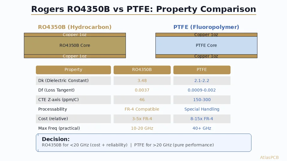
| Property | Rogers RO4350B | RO3003 (PTFE) | RT/duroid 5880 (PTFE) |
|---|---|---|---|
| Dk @ 10 GHz | 3.48 ±0.05 | 3.00 ±0.04 | 2.20 ±0.02 |
| Df @ 10 GHz | 0.0037 | 0.0013 | 0.0009 |
| Df @ 28 GHz | ~0.0045 | ~0.0016 | ~0.0012 |
| Insertion loss @ 28 GHz | ~1.2 dB/in | ~0.5 dB/in | ~0.4 dB/in |
| FR-4 process compatible | Yes | No | No |
| Dimensional stability | Excellent | Moderate | Poor |
| Drill registration | Standard | Requires care | Difficult |
| Cost ($/sq ft) | $80-120 | $150-200 | $180-250 |
| Typical fab yield | 92-96% | 80-88% | 75-85% |
The numbers tell the story: PTFE delivers 3x lower loss but at the cost of 10-20% lower manufacturing yield and 2-3x material expense.
28 GHz Feed Network Design: Where RO4350B Works
At 28 GHz (n257/n258 bands), the practical question is whether your antenna array feed network is short enough for RO4350B’s higher loss to remain within your system link budget.
For a 4x4 patch array with corporate (parallel) feed topology, the longest feed path from connector to edge element is typically 1.5-2.2 inches depending on element spacing (typically λ/2 = 5.4mm at 28 GHz). With RO4350B’s ~1.2 dB/inch at 28 GHz, this translates to 1.8-2.6 dB of feed network loss.
Compare to system-level requirements: a typical 5G mmWave front-end module allocates 3-4 dB total insertion loss budget for the antenna PCB (including feed network, transitions, and connector). With 2-2.5 dB consumed by the feed network in RO4350B, you have 1-1.5 dB remaining for transitions and connector losses — tight but achievable with well-designed GCPW-to-microstrip transitions and high-quality end-launch connectors.
For smaller arrays (2x2, 4x1) with shorter feed paths under 1.5 inches, RO4350B is clearly adequate — the total feed loss stays under 2 dB with comfortable margin for manufacturing variation.
5G ANTENNA PCB FABRICATION
Rogers and PTFE Antenna Arrays — From Prototype to Production
We fabricate 5G mmWave antenna PCBs in RO4350B, RO3003, and RT/duroid daily. Hybrid stackups with verified phase consistency across array elements.
39 GHz: Where PTFE Becomes Mandatory
At 39 GHz (n260 band), the equation shifts decisively toward PTFE. RO4350B’s loss tangent increases to approximately 0.005 at this frequency, translating to ~1.6 dB/inch insertion loss. For any feed network longer than 1 inch, this accumulates rapidly.
A 4x4 array at 39 GHz has tighter element spacing (λ/2 = 3.8mm) which reduces physical feed length somewhat, but the increased per-inch loss more than compensates. The longest feed path in a corporate-fed 4x4 drops to approximately 1.2-1.8 inches, but at 1.6 dB/inch, total loss reaches 2-3 dB — consuming most or all of the link budget before accounting for transitions and connectors.
PTFE materials (RO3003 at ~0.6 dB/inch, RT/duroid 5880 at ~0.5 dB/inch at 39 GHz) keep the same feed network within 0.6-1.0 dB total — leaving adequate margin for the rest of the RF chain.
For 39 GHz designs, our recommendation is unambiguous: use PTFE for the antenna and feed layers, accepting the manufacturing complexity and cost premium as non-negotiable requirements of the frequency band.
Hybrid Stackup Strategy: The Production-Optimized Approach
For phased array production at 28 GHz, hybrid stackups offer the best balance of performance and manufacturability. The concept: use PTFE where its low loss matters most (radiating elements), and RO4350B where manufacturability matters most (complex feed routing with tight trace geometries).
Recommended 6-Layer Hybrid for 28 GHz 4x4 Array
| Layer | Material | Thickness | Function |
|---|---|---|---|
| L1 | RT/duroid 5880 | 10 mil | Patch antenna elements |
| Bond | RO4450F | 4 mil | Rogers-compatible bondply |
| L2 | Copper (GND) | 1 oz | Ground plane / cavity |
| Core | RO4350B | 12 mil | Feed distribution core |
| L3 | Copper (Feed) | 0.5 oz | Corporate feed network |
| Bond | RO4450F | 4 mil | |
| L4 | Copper (GND) | 1 oz | Feed reference plane |
| Core | FR-4 | 20 mil | Structural/DC bias |
| L5 | Copper (DC) | 1 oz | DC bias distribution |
| Bond | FR-4 prepreg | 4 mil | Standard bonding |
| L6 | Copper (Digital) | 0.5 oz | Control signals |
This stackup isolates the lossy elements: the antenna patches radiate through the lowest-loss PTFE layer, while the feed network on L3 uses RO4350B for its short runs. The FR-4 structural core adds mechanical rigidity without affecting RF performance since it is shielded between ground planes.
Manufacturing advantage: the most complex routing (feed network with 3-4mil traces and tight spacing) is on the RO4350B layer where etch uniformity and registration are well-controlled. The PTFE layer has only patch geometries — relatively simple large features that tolerate PTFE’s dimensional challenges.
HYBRID STACKUP ENGINEERING
Custom Hybrid Stackups for mmWave Arrays
We design and fabricate hybrid PTFE/Rogers/FR-4 stackups optimized for your array architecture. Free stackup review with impedance simulation included in quote.
Submit Stackup for Review ›Manufacturing Reality: Why PTFE Yield Matters at Volume
The yield difference between RO4350B and PTFE is not just a cost issue — it affects delivery timelines and production planning. In our production data:
- RO4350B antenna boards: 93% first-pass yield (consistent with standard FR-4 processes)
- PTFE antenna boards: 82% first-pass yield (driven by registration, delamination, and drill smear)
- Hybrid PTFE/Rogers: 87% first-pass yield (improved by limiting PTFE to simpler geometry layers)
For a 500-piece production run, these yield differences translate to:
- RO4350B: Build 540 panels to deliver 500 (7% overproduction)
- PTFE: Build 610 panels to deliver 500 (22% overproduction)
- Hybrid: Build 575 panels to deliver 500 (15% overproduction)
The 15% yield gap between pure PTFE and RO4350B means more material consumed, longer production runs, and higher risk of delivery delays if yield drops below plan. For ongoing production programs, this reliability difference compounds over time.
PTFE-Specific Failure Modes We Monitor
Copper adhesion failure: PTFE’s chemical inertness requires surface activation (sodium etch or plasma) before copper bonding. Incomplete activation creates latent adhesion defects that pass visual inspection but fail peel strength testing. Our incoming inspection includes 100% peel strength verification on PTFE panels.
Registration drift during lamination: PTFE’s high CTE mismatch versus copper creates dimensional changes during the press cycle. For antenna arrays where patch element placement accuracy determines beam pointing, this drift directly affects far-field performance. We compensate artwork based on measured shrink factors for each PTFE material lot.
Via barrel cracking: The CTE mismatch between PTFE (Z-axis CTE ~250 ppm/C) and plated copper via barrels (~17 ppm/C) creates thermal stress during reflow. For antenna PCBs seeing multiple reflow cycles, via reliability testing (IST) validates long-term survival.
Phase Consistency Across Array Elements
For phased arrays, material consistency directly affects beam steering accuracy. Dk variation across the PCB creates phase errors between antenna elements — if the feed to each element sees slightly different effective dielectric constant, the resulting phase shift degrades the array pattern.
| Material | Dk tolerance | Phase error per λ | Impact on 4x4 array sidelobe |
|---|---|---|---|
| RO4350B | ±0.05 (±1.4%) | ±5° per wavelength | <0.5 dB sidelobe rise |
| RO3003 | ±0.04 (±1.3%) | ±4.7° per wavelength | <0.5 dB sidelobe rise |
| RT/duroid 5880 | ±0.02 (±0.9%) | ±3.2° per wavelength | <0.3 dB sidelobe rise |
| Generic PTFE | ±0.10 (±4.5%) | ±16° per wavelength | 2-3 dB sidelobe rise |
All three Rogers materials provide adequate Dk consistency for phased array work. The critical distinction is between branded materials with tight process control versus generic PTFE from uncharacterized sources. We source exclusively from authorized Rogers distributors with lot-traceable material certifications.
MATERIAL TRACEABILITY
Authorized Rogers Material — Lot-Traceable, Dk-Verified
Every Rogers and PTFE panel we process is sourced from authorized distributors with full lot traceability. Material test reports included in shipment for your records.
View RF Material Capabilities ›Decision Framework: RO4350B vs PTFE for Your 5G Antenna
Use Rogers RO4350B when:
- Operating frequency is 28 GHz or below
- Feed network total path length is under 2 inches
- Your link budget can accommodate 1.2 dB/inch loss at frequency
- Production volume demands high yield consistency
- Array size is 4x4 or smaller with corporate feed
- Cost target requires sub-$500 per prototype board
- You need standard PCB process compatibility (broader supplier base)
Use PTFE (RO3003 or RT/duroid 5880) when:
- Operating frequency exceeds 35 GHz
- Feed network path exceeds 3 inches
- Link budget requires less than 0.6 dB/inch loss
- Antenna radiation efficiency is critical (>90% target)
- Application is 39 GHz (n260) or above
- Prototype-only with no production volume requirement
Use Hybrid PTFE/RO4350B when:
- Operating at 28-39 GHz with large arrays (8x8+)
- Need PTFE antenna efficiency with reliable feed fabrication
- Production volumes exceed 100 pieces (yield matters)
- Budget allows moderate premium over pure RO4350B
- Array architecture separates antenna and feed into distinct layers
ATLASPCB — CHINA RF PCB MANUFACTURER
5G mmWave Antenna PCB Fabrication — Rogers, PTFE, Hybrid
From 24 GHz automotive radar to 39 GHz 5G fixed wireless — we fabricate antenna array PCBs with verified phase consistency and insertion loss testing. Prototype through 10K+ production volumes.
Get 5G Antenna PCB Quote ›Reviewed by AtlasPCB Engineering Team — 15+ years in advanced PCB fabrication for RF, HDI, and rigid-flex applications.
Related Reading:
About AtlasPCB — We specialize in complex PCB manufacturing for HDI, RF, and high-reliability applications. Explore our RF and high-frequency PCB services, or get an multilayer PCB fabrication up to 30 layers . Every order includes free engineering review. Get your quote.
Reviewed by AtlasPCB Engineering Team — IPC-certified manufacturing specialists with 15+ years of production experience in HDI, RF, and high-reliability PCB fabrication. Content based on factory floor data and real customer design reviews.
- Rogers 4350B stackup
- 5G antenna PCB fabrication
- RF PCB design and manufacturing
- Rogers PCB manufacturer
- China RF PCB manufacturer