· AtlasPCB Engineering · Engineering · 9 min read
FR-4 vs Rogers PCB: Complete Material Selection Guide for RF and High-Speed Design
FR-4 or Rogers? Compare dielectric loss, thermal stability, cost, and fabrication compatibility to choose the right PCB material for your frequency range and budget constraints.
The 30-Second Decision
| Parameter | Standard FR-4 | Rogers RO4350B | When It Matters |
|---|---|---|---|
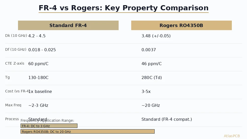
| Dk @ 10 GHz | 4.2-4.5 (varies with resin) | 3.48 (+/-0.05) | Impedance predictability |
| Df @ 10 GHz | 0.018-0.025 | 0.0037 | Insertion loss at frequency |
| Dk stability vs temp | +/-10% over 25-125C | +/-1.5% over -40 to +150C | Environmental reliability |
| CTE (Z-axis) | 60-70 ppm/C | 46 ppm/C | Via reliability in thermal cycling |
| Tg / Td | 130-180C / 300C | N/A / 390C (Td) | Lead-free reflow margin |
| Cost multiplier | 1x (baseline) | 3-5x | Budget-constrained designs |
| Max practical freq | ~1-3 GHz | ~20 GHz | Application frequency |
| Fabrication process | Standard | Standard (FR-4 compatible) | Supplier availability |
Decision rule: If your critical signal paths operate above 2 GHz and total trace length exceeds 2 inches, the insertion loss penalty of FR-4 will likely push you to Rogers. Below 1 GHz with reasonable trace lengths, FR-4 is more than adequate and significantly cheaper.
Why Dielectric Loss Is the Real Decision Driver
The choice between FR-4 and Rogers ultimately comes down to one number: loss tangent (Df). Everything else — cost, availability, thermal performance — is secondary to whether your signal arrives at the receiver with enough amplitude to meet your link budget.
At 1 GHz, the difference between FR-4 (Df 0.020) and Rogers RO4350B (Df 0.0037) translates to roughly 0.3 dB/inch versus 0.06 dB/inch of dielectric loss. Over a 3-inch trace, that is 0.9 dB versus 0.18 dB — often acceptable for most digital interfaces and low-frequency RF.
At 10 GHz, the math changes dramatically. FR-4 dielectric loss scales to approximately 2.5 dB/inch while Rogers stays at 0.6 dB/inch. A 2-inch feed line to an antenna connector now costs you 5 dB in FR-4 versus 1.2 dB in Rogers. For an RF front-end with a typical 3 dB noise figure, that 3.8 dB of unnecessary loss directly degrades your system sensitivity by the same amount — equivalent to halving your receiver range.
In our production experience across hundreds of RF boards, we consistently see engineers underestimate trace-loss impact during schematic design, then discover margin problems during the first prototype. The material decision needs to happen at the stackup planning stage, not after layout is complete.
RF MATERIAL EXPERTISE
Not Sure Which Material Fits Your Frequency?
Our RF engineers review your stackup requirements and recommend the optimal material — FR-4, Rogers, or hybrid — based on your frequency, loss budget, and cost targets.
Get Material Recommendation ›Fabrication Compatibility: Where Rogers Wins Over Other RF Materials
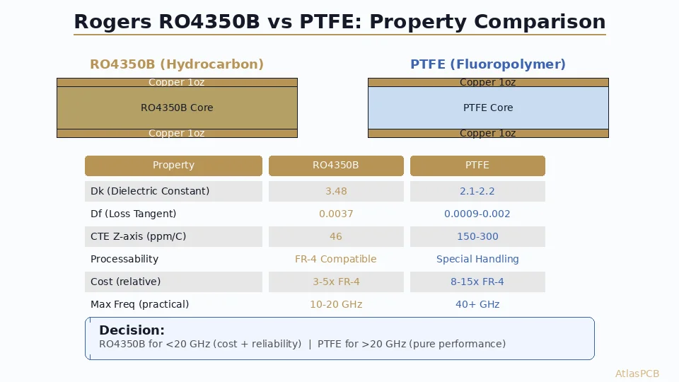
One of the most overlooked advantages of Rogers RO4350B is its fabrication compatibility with standard FR-4 processes. Unlike PTFE materials (Rogers RT/duroid, Taconic TLY) which require specialized drilling, plasma desmear, and adhesion promoters, RO4350B drops into existing FR-4 production lines with minimal process changes.
In our facility, we process RO4350B on the same drill machines, plating lines, and lamination presses as standard FR-4. The only meaningful process adjustment is lamination temperature — RO4350B bonds optimally at 390F versus 350F for most FR-4 prepregs. This compatibility means shorter lead times, fewer qualified-supplier constraints, and significantly lower NRE costs compared to PTFE alternatives.
The fabrication story differs entirely for pure PTFE materials. PTFE’s naturally low surface energy makes copper adhesion challenging, requiring plasma treatment or proprietary adhesion layers. Drilling PTFE generates heat that smears the soft material across via walls, necessitating plasma desmear rather than standard chemical processes. These additional steps limit the number of qualified fabricators, extend lead times by 1-2 weeks, and increase per-board costs by 30-50% beyond the already-higher material cost.
For engineers choosing between Rogers and competing RF materials, this fabrication simplicity translates directly to supply chain resilience. Any competent multilayer fabricator can produce your RO4350B board. With PTFE, you are likely limited to 3-5 qualified shops, creating single-source risk.
Thermal and Mechanical Reliability Compared
CTE Mismatch and Via Reliability
Coefficient of thermal expansion (CTE) differences between materials in a multilayer stackup create mechanical stress during thermal cycling — particularly at plated via barrels. FR-4’s Z-axis CTE of 60-70 ppm/C expands significantly more than copper (17 ppm/C), creating tensile stress on via walls during reflow and thermal excursions.
Rogers RO4350B’s Z-axis CTE of 46 ppm/C is notably better than FR-4, reducing via barrel stress by approximately 30% under equivalent thermal conditions. For applications requiring IPC Class 3 reliability (aerospace, medical, automotive), this CTE advantage translates directly to longer thermal cycling life.
We’ve run IST (Interconnect Stress Testing) on comparative stackups and consistently measure 20-30% longer cycles-to-failure on Rogers constructions versus equivalent FR-4 builds at the same layer count. For missions requiring 1000+ thermal cycles at -55 to +125C, the Rogers advantage is significant enough to influence material selection independent of electrical considerations.
Moisture Absorption
FR-4 absorbs 0.10-0.15% moisture by weight under standard conditions, which shifts Dk by 1-3% depending on humidity exposure. Rogers RO4350B absorbs just 0.06% — making it far more stable in humid environments and less susceptible to delamination during lead-free reflow after board storage.
IMPEDANCE CONTROLLED MANUFACTURING
Tight Impedance Tolerance on Rogers and FR-4
We hold +/-5% impedance tolerance on Rogers stackups and +/-7% on FR-4 as standard. TDR-verified on every impedance-controlled lot.
Cost Analysis: When Rogers Justifies the Premium
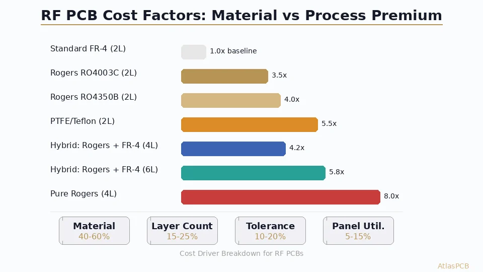
The raw material cost difference between FR-4 and Rogers RO4350B is substantial but not always the deciding factor in total board cost. Understanding where the premium comes from helps engineers optimize their material spending.
Material Cost Breakdown (per panel, 18x24 inch)
| Material | Cost/Panel | Availability | MOQ |
|---|---|---|---|
| Standard FR-4 (Tg 150) | $25-40 | 1-2 day stock | None |
| High-Tg FR-4 (Tg 170) | $35-55 | 1-3 day stock | None |
| Rogers RO4350B (10mil) | $180-250 | 1-2 week lead | 5 panels |
| Rogers RO4350B (20mil) | $220-320 | 1-2 week lead | 5 panels |
| Rogers RT5880 (10mil PTFE) | $350-500 | 2-4 week lead | 10 panels |
Hybrid Stackup Cost Optimization
The most effective cost reduction strategy for RF boards is to limit Rogers material to only the layers that carry RF signals. A typical 6-layer hybrid stackup might use RO4350B for layers 1-2 (RF), standard FR-4 for layers 3-4 (digital/power), and Rogers or FR-4 for layers 5-6 depending on whether the bottom carries RF as well.
In our experience producing 50+ hybrid Rogers/FR-4 designs monthly, the typical cost saving versus an all-Rogers stackup is 40-60% while maintaining identical RF performance on the critical layers. The key is ensuring your stackup designer accounts for the slightly different prepreg requirements at the Rogers-to-FR-4 bonding interface — we use Rogers 4450F prepreg or Isola 185HR at this transition.
When FR-4 Is the Wrong Compromise
We occasionally see engineers force FR-4 on designs that clearly need Rogers, driven by procurement cost pressure. The resulting prototype failures — missed impedance targets, excessive insertion loss, failed compliance testing — end up costing 2-3x more in respins than the Rogers material would have added. If your design includes any of the following, Rogers is almost certainly necessary:
- RF signal paths above 3 GHz with length exceeding 1 inch
- Impedance tolerance requirement of +/-5% or tighter
- Operating environment cycling beyond -20 to +85C
- Antenna feed networks at any microwave frequency
- Millimeter-wave applications (24 GHz and above)
CHINA RF PCB MANUFACTURER
Rogers PCB at China-Direct Pricing
We stock RO4350B, RO4003C, and RT5880 in standard thicknesses. Get your Rogers PCB quoted in 2 hours with material availability confirmed upfront.
Compare Prices ›Application Decision Matrix
By Industry and Frequency
| Application | Typical Freq | Recommended Material | Rationale |
|---|---|---|---|
| IoT/BLE | 2.4 GHz | FR-4 (High-Tg) | Short traces, cost-sensitive |
| WiFi 6E | 6 GHz | Rogers RO4350B | Loss budget tight at 6 GHz |
| 5G Sub-6 | 3.5-6 GHz | Rogers RO4350B | Base station demands low PIM |
| X-band radar | 8-12 GHz | Rogers RO4350B | Acceptable loss for moderate path |
| Ku-band SATCOM | 12-18 GHz | Rogers RO4350B/RO3003 | Performance ceiling of thermoset |
| 5G mmWave | 24-40 GHz | Rogers RT5880 or PTFE | Only PTFE works at mmWave |
| 77 GHz auto radar | 76-81 GHz | PTFE (RT5880, TLY-5) | Mandatory for loss budget |
The JLCPCB vs Custom Manufacturer Question
Many engineers start prototyping at budget PCB services (JLCPCB, PCBWay) using FR-4, then discover they need Rogers for production. Budget services typically offer limited Rogers options — often only RO4350B in 2 or 4 layers with wider tolerances. A specialized RF PCB manufacturer provides:
- Full Rogers material library (RO4350B, RO4003C, RT5880, TMM series)
- Hybrid Rogers/FR-4 stackups with proper transition prepregs
- Tighter impedance tolerance (+/-5% vs +/-10%)
- Higher layer counts with Rogers (up to 12+ layers)
- Engineering support for stackup optimization
For prototypes where you are validating functionality, budget services work fine with FR-4. Once your design is proven and moving toward production — especially if RF performance is critical to your product — partnering with a manufacturer that specializes in Rogers fabrication avoids the common pitfall of discovering process limitations at the worst possible time.
Summary: Making the Material Call
The FR-4 vs Rogers decision follows a simple logic tree:
- Operating frequency below 1 GHz, trace lengths under 6 inches: FR-4 is fine. Save your budget.
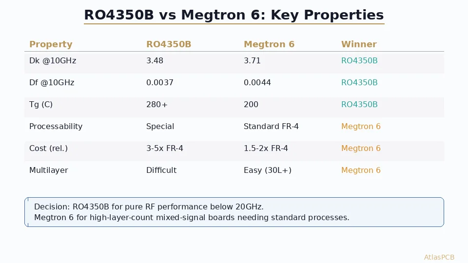
- 1-3 GHz with traces over 2 inches: Evaluate your loss budget. High-Tg FR-4 or low-loss laminate (IS680, Megtron 4) may suffice. Rogers is the safe choice.
- 3-20 GHz: Rogers RO4350B is the default answer. FR-4 is unsuitable.
- Above 20 GHz: PTFE-based Rogers (RT5880, RO3003) is mandatory. No thermoset material works here.
The hybrid stackup approach — Rogers where RF signals live, FR-4 everywhere else — gives you optimal performance at minimum cost. It is the approach we recommend and fabricate most frequently for customers building mixed-signal systems with both high-speed digital and RF functionality.
ATLASPCB
Ready to Order Your RF PCB?
Upload your Gerber files and stackup requirements. We quote Rogers, FR-4, and hybrid builds with material availability confirmed within 2 hours.
Get Instant Quote ›Reviewed by AtlasPCB Engineering Team — 15+ years in advanced PCB fabrication for RF, HDI, and rigid-flex applications.
Related Reading:
About AtlasPCB — We specialize in complex PCB manufacturing for HDI, RF, and high-reliability applications. Explore our RF and high-frequency PCB services, or get an impedance-controlled PCB manufacturing . Every order includes free engineering review. Get your quote.
Reviewed by AtlasPCB Engineering Team — IPC-certified manufacturing specialists with 15+ years of production experience in HDI, RF, and high-reliability PCB fabrication. Content based on factory floor data and real customer design reviews.
- FR-4
- Rogers
- RF PCB
- PCB material selection
- RO4350B
- high frequency
- impedance controlled PCB