· AtlasPCB Engineering · Engineering · 6 min read
Rogers RO4350B vs PTFE for RF PCB: Material Selection Guide for 5G, Radar, and mmWave
Choosing between Rogers RO4350B and PTFE for your RF PCB? Compare dielectric properties, thermal reliability, fabrication compatibility, and cost to make the right material decision for your frequency range.
The 30-Second Decision
| Criteria | Rogers RO4350B | PTFE (RT5880, TLY-5) |
|---|---|---|
| Best for | 1-20 GHz applications | 20-77+ GHz applications |
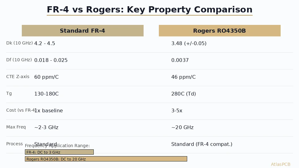
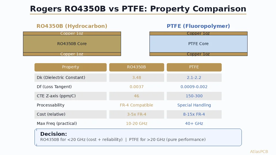
| Dk | 3.48 (+/-0.05) | 2.1-2.2 (+/-0.02) |
| Df @ 10 GHz | 0.0037 | 0.0009-0.002 |
| CTE Z-axis | 46 ppm/C | 150-300 ppm/C |
| Fabrication | Standard FR-4 process | Special handling required |
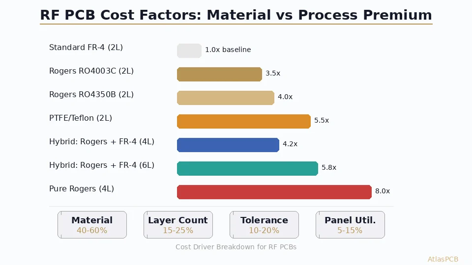
| Cost vs FR-4 | 3-5x | 8-15x |
| Multilayer ease | Drop-in replacement | Challenging, limited fabs |
Bottom line: If your design operates below 20 GHz and needs multilayer integration, RO4350B wins on cost, reliability, and supply chain. If you’re pushing above 20 GHz and every 0.1 dB/inch matters, PTFE is the only path.
Dielectric Properties: Where the Physics Diverges
Dielectric Constant (Dk)
RO4350B’s Dk of 3.48 means narrower traces for a given impedance compared to PTFE’s 2.1-2.2. At 50 ohms on a 10-mil substrate:
- RO4350B: ~22 mil trace width (microstrip)
- PTFE (Dk 2.2): ~30 mil trace width (microstrip)
Wider traces on PTFE mean lower conductor loss at high frequencies—a double benefit alongside the lower dielectric loss.
Loss Tangent (Df) — The Critical Differentiator
At 10 GHz, RO4350B’s Df of 0.0037 produces approximately 0.8 dB/inch insertion loss on a 50-ohm microstrip. PTFE at Df 0.0009 drops that to 0.3 dB/inch.
At 77 GHz (automotive radar), this gap becomes dramatic:
- RO4350B: ~6-8 dB/inch (often unusable)
- PTFE: ~2-3 dB/inch (workable for short runs)
Dk Stability Over Temperature
RO4350B: +/-50 ppm/C drift — excellent for filters and coupled-line structures that need stable electrical length.
PTFE: +/-100-200 ppm/C — adequate, but less predictable at temperature extremes. Pure PTFE (unfilled) can exhibit a crystalline phase transition near 19C that causes a Dk step change.
RF PCB MATERIALS
Not Sure Which Material Fits Your Frequency?
Our engineers work with Rogers, Taconic, and Isola RF materials daily. Upload your stackup for a material recommendation.
Get Material Recommendation ›Fabrication Reality: Why Processability Matters
RO4350B: The FR-4 Compatible RF Material
Rogers designed the 4000 series specifically to eliminate PTFE’s fabrication headaches:
- Drilling: Standard carbide bits, same parameters as FR-4
- Desmear: Standard permanganate chemical process
- Plating: Standard electroless copper adhesion—no plasma treatment needed
- Lamination: Compatible with standard FR-4 prepregs (Rogers 4450F recommended)
- Solder mask: Standard LPI application, no adhesion promoters
- Lead-free compatible: Td > 390C, handles multiple reflow cycles
This means any fabricator that handles FR-4 multilayers can process RO4350B with minimal process changes. Lead times are comparable to standard boards.
PTFE: High Performance, High Maintenance
PTFE’s fluoropolymer chemistry creates fabrication challenges:
- Drilling: Requires fresh, sharp bits (PTFE dulls carbide 3-5x faster). Burr formation is common without optimized parameters.
- Desmear: Must use plasma (gas-phase) desmear—standard chemical desmear doesn’t attack PTFE. Adds a process step and equipment requirement.
- Copper adhesion: PTFE’s surface energy is extremely low (non-stick). Requires sodium naphthalenide etch or plasma treatment before plating.
- Dimensional stability: PTFE stretches during handling. Registration challenges in multilayer builds.
- CTE mismatch: Z-axis CTE of 150-300 ppm/C vs copper’s 17 ppm/C creates reliability risk in PTH vias.
The practical result: fewer fabricators are qualified, lead times are longer, yields are lower, and costs reflect all of this.
Thermal Reliability: The CTE Problem
CTE mismatch between substrate and copper drives via barrel cracking in thermal cycling. Here’s the comparison:
| Property | RO4350B | PTFE | FR-4 (reference) |
|---|---|---|---|
| CTE X/Y (ppm/C) | 14/16 | 16/16 | 14/16 |
| CTE Z (ppm/C) | 46 | 150-300 | 50-70 |
| Td (decomposition) | 390C | 500C+ | 310C |
| T260 (minutes) | 30+ | 60+ | 5-10 |
RO4350B’s Z-axis CTE of 46 ppm/C is better than FR-4 and dramatically better than unfilled PTFE. This translates to superior PTH reliability—critical for boards facing thermal cycling (automotive, aerospace, power electronics).
Ceramic-filled PTFE variants (Rogers RT/duroid 6002, Dk=2.94) reduce CTE to ~24 ppm/C Z-axis but sacrifice the ultra-low Dk that makes pure PTFE attractive.
PROVEN RELIABILITY
RF Boards with IST-Verified Via Reliability
Our high-frequency PCB line handles Rogers and PTFE materials with thermal cycling validation per IPC-TM-650.
View RF PCB Capabilities ›Application Decision Matrix
| Application | Frequency | Recommended | Reason |
|---|---|---|---|
| 5G Sub-6 GHz antenna | 3.5-6 GHz | RO4350B | Adequate loss, easy multilayer |
| WiFi 6E/7 | 6 GHz | RO4350B | Cost-effective, standard fab |
| X-band radar | 8-12 GHz | RO4350B | Good balance of performance/cost |
| Ku-band satellite | 12-18 GHz | RO4350B or hybrid | Marginal—test both |
| 5G mmWave (FR2) | 24-39 GHz | PTFE or hybrid | Loss budget demands PTFE |
| 77 GHz automotive radar | 76-81 GHz | PTFE | Only viable option |
| 60 GHz WiGig | 57-71 GHz | PTFE | Short traces help, but PTFE needed |
| E-band backhaul | 71-86 GHz | PTFE | No alternative at these frequencies |
The Hybrid Approach
For designs mixing RF front-end with digital back-end, a hybrid stackup saves cost:
- RF layers: PTFE core (signal + adjacent ground)
- Digital layers: FR-4 or RO4350B
- Bonding: Rogers 4450F or Taconic FastRise-27 prepreg
This works well for 5G massive MIMO antenna boards where only 2 of 8+ layers carry RF signals.
HYBRID STACKUP EXPERTISE
Mixed-Material RF Stackups Done Right
We fabricate hybrid Rogers/PTFE/FR-4 stackups with controlled impedance on every RF layer. Send your stackup for DFM feedback.
Upload Stackup ›Cost Comparison: Real Numbers
For a 4-layer, 100x80mm RF board (10-piece prototype, ENIG finish):
| Material | Material Cost | Fab Premium | Total vs FR-4 |
|---|---|---|---|
| FR-4 (baseline) | $12-18/panel | — | $150-250 |
| RO4350B (all layers) | $45-80/panel | +20% | $350-550 |
| PTFE RT5880 (all layers) | $120-200/panel | +80% | $800-1400 |
| Hybrid (2x PTFE + 2x FR-4) | $70-100/panel | +40% | $450-700 |
At production volumes (1000+ boards), the per-unit gap narrows but the ranking stays the same. RO4350B is 3-5x FR-4; PTFE is 8-15x FR-4.
The Hidden Costs of PTFE
Beyond material price, PTFE adds:
- Longer lead time: +5-10 days (fewer qualified fab lines)
- Lower yield: 85-90% vs 95%+ for RO4350B
- Rework risk: Delamination during rework is more likely
- Supply chain: Fewer second sources, longer material lead times
Summary Decision Framework
- Frequency below 10 GHz → RO4350B (no contest)
- 10-20 GHz → RO4350B default; evaluate loss budget carefully
- 20-40 GHz → Hybrid stackup or PTFE depending on trace lengths
- Above 40 GHz → PTFE required
Secondary factors:
- Need multilayer (8+ layers)? RO4350B is far easier
- Automotive qualification needed? RO4350B’s CTE wins
- Cost-sensitive volume product? RO4350B every time
- Maximum performance at any cost? PTFE
ATLASPCB
Ready to Quote Your RF Board?
We stock Rogers RO4350B, RO4003C, and work with PTFE suppliers for fast-turn RF prototypes. Upload your Gerber files for an instant quote.
Get Instant Quote ›Related Reading:
About AtlasPCB — We specialize in complex PCB manufacturing for HDI, RF, and high-reliability applications. Explore our RF and high-frequency PCB services . Every order includes free engineering review. Get your quote.
Reviewed by AtlasPCB Engineering Team — IPC-certified manufacturing specialists with 15+ years of production experience in HDI, RF, and high-reliability PCB fabrication. Content based on factory floor data and real customer design reviews.
- Rogers RO4350B
- PTFE
- RF PCB
- high frequency
- mmWave
- 5G
- dielectric constant
- PCB material