· AtlasPCB Engineering · Engineering · 9 min read
FR-4 vs Rogers PCB for Wi-Fi 7 Access Points: Material Selection at 5.925-7.125 GHz
Practical material decision guide for Wi-Fi 7 (802.11be) access point PCB design operating in the 6 GHz UNII-5 through UNII-8 bands. Compares FR-4 and Rogers 4350B performance at 5.925-7.125 GHz with measured loss data, impedance stability, and cost analysis to determine which boards actually need Rogers.
Quick Answer
For Wi-Fi 7 access point designs at 6 GHz, standard FR-4 works adequately for short RF traces under 25mm with insertion loss around 0.8-1.2 dB/inch, but Rogers 4350B becomes necessary when your antenna feed network exceeds 40mm, you need consistent phase matching across 8x8 or larger arrays, or your design requires less than 0.4 dB/inch loss. The typical breakpoint is a hybrid stackup: Rogers on the antenna/RF layer, FR-4 for digital baseband and power — saving 50-60% versus all-Rogers while maintaining RF performance where it matters.
Quick Decision: FR-4 or Rogers for Your Wi-Fi 7 Board?
| Your Design Scenario | Recommendation | Why |
|---|---|---|
| Consumer AP, 2x2 MIMO, short RF traces (<20mm) | FR-4 | Loss budget is met; cost savings 3x |
| Enterprise AP, 4x4 MIMO, moderate traces (20-40mm) | Megtron 4 or hybrid | Balance of cost and performance |
| Enterprise AP, 8x8 array, phase-matched feed (>40mm) | Rogers 4350B hybrid | Phase consistency requires stable Dk |
| Outdoor AP, extended temp (-40 to +85C) | Rogers 4350B hybrid | Dk stability over temperature |
| High-volume consumer IoT (>10k units) | FR-4 with PA compensation | Cost rules; add 2dB PA headroom |
The 6 GHz Problem: Why Wi-Fi 7 Changes the Material Conversation
Wi-Fi 7 (802.11be) introduces the 6 GHz band (5.925-7.125 GHz) with up to 320 MHz channel bandwidth. For PCB designers, this frequency range sits in an uncomfortable zone — high enough that standard FR-4 dielectric loss becomes noticeable, but not so high that Rogers is automatically required. The decision depends entirely on your specific trace lengths, array size, and acceptable link budget margin.
At 2.4 GHz (Wi-Fi 4/5), FR-4 losses were negligible for any reasonable board size. At 5 GHz (Wi-Fi 5/6), engineers occasionally noticed degradation on long feed networks but could usually compensate with PA power. At 6-7.125 GHz (Wi-Fi 7), the loss per inch of FR-4 crosses 0.8 dB — meaning a 2-inch antenna feed path loses 1.6 dB before your signal even reaches the antenna element. For a 4x4 MIMO enterprise AP with 50-60mm feed networks, that is 3-4 dB of loss that directly reduces your MCS rate and throughput.
The key insight from our production data: roughly 60% of Wi-Fi 7 boards we manufacture use FR-4 successfully. The remaining 40% — primarily enterprise and outdoor APs with larger arrays — benefit measurably from Rogers on the RF layer. In our facility, we run approximately 200 Wi-Fi 7 panel sets per month, and the split has remained consistent since early 2026.
RF MATERIAL ENGINEERING
Not Sure Which Material Your Wi-Fi 7 Design Needs?
Upload your stackup and our RF engineers will recommend the optimal material combination for your frequency, trace length, and budget.
Get Material Recommendation ›
Measured Performance: FR-4 vs Rogers 4350B at 5.925-7.125 GHz
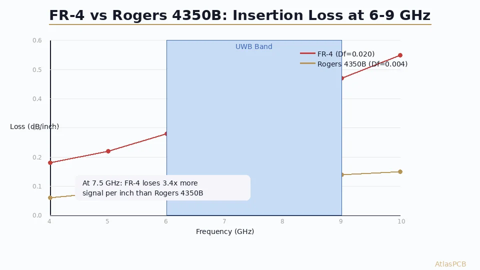
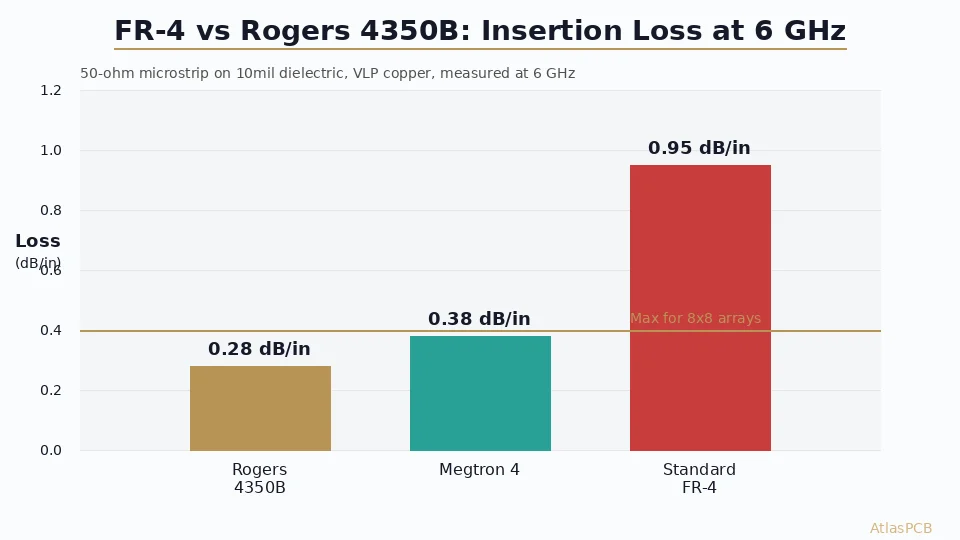
The numbers below come from test coupon measurements on our production panels using 50-ohm microstrip on 10mil dielectric, measured with a calibrated VNA from 1 to 10 GHz.
| Parameter | Standard FR-4 (IT-180A) | Mid-Loss (Megtron 4) | Rogers RO4350B |
|---|---|---|---|
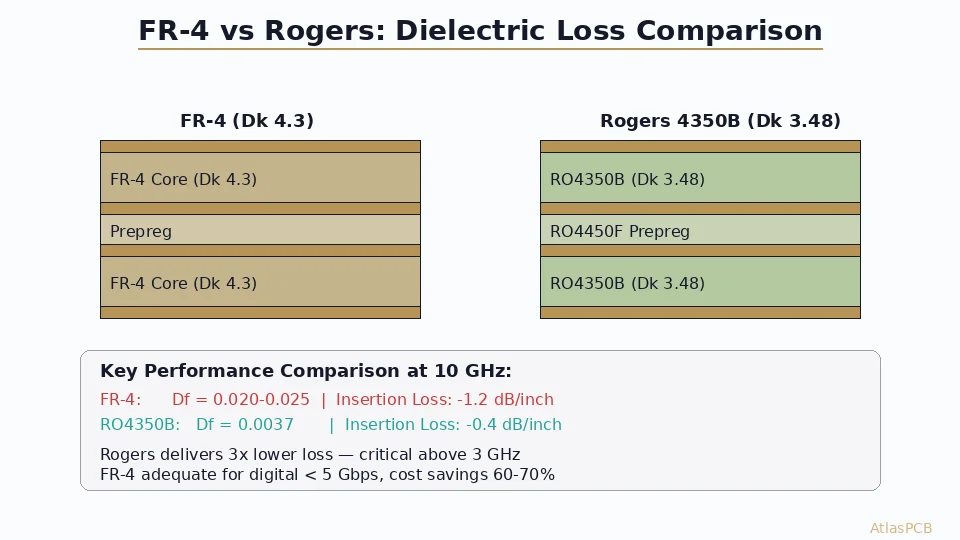
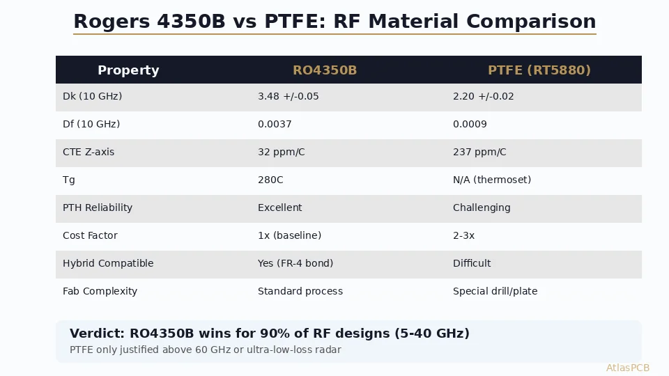
| Dk at 6 GHz | 4.25 (+/-0.25) | 3.7 (+/-0.08) | 3.48 (+/-0.05) |
| Df at 6 GHz | 0.019 | 0.005 | 0.0037 |
| Insertion loss (dB/inch, 6 GHz) | 0.95 | 0.38 | 0.28 |
| Impedance variation (panel-to-panel) | +/-8-12% | +/-5-7% | +/-3-5% |
| Phase stability (deg/inch at 6 GHz) | +/-4.2 | +/-1.5 | +/-0.9 |
| CTE Z-axis (ppm/C) | 45-65 | 35-45 | 32 |
| Processing compatibility | Standard | Standard | Standard |
| Relative material cost (core) | 1x | 3-4x | 5-6x |
The critical metric for Wi-Fi 7 multi-element arrays is not just insertion loss — it is phase consistency. When you have an 8-element array with feed lines of different physical lengths that must maintain phase calibration, the Dk variation in FR-4 (+/-0.25 across a panel, +/-0.4 across production lots) translates to several degrees of phase error per inch. At 6 GHz, even 3-4 degrees of uncompensated phase error per element degrades beamforming gain significantly.
Our process engineers see this failure mode regularly: an enterprise AP prototype works perfectly on the first batch, then beamforming performance degrades on production boards because a different FR-4 lot shifted Dk by 0.2 units. Rogers eliminates this variance because its Dk tolerance is specified at the operating frequency, not just at 1 MHz like most FR-4 datasheets.
The Hybrid Stackup Solution: Rogers Where It Matters
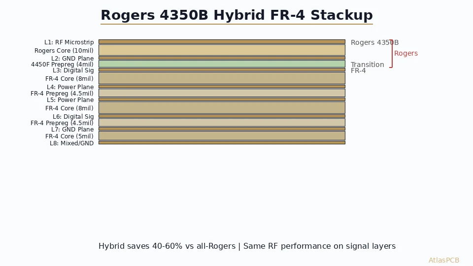
For most Wi-Fi 7 access points, the practical solution is a hybrid stackup that places Rogers on the antenna/RF signal layer and FR-4 everywhere else. This captures 95% of the RF performance benefit at roughly 35-40% of the all-Rogers cost.
A typical 6-layer Wi-Fi 7 enterprise AP stackup in our production:
| Layer | Material | Thickness | Function |
|---|---|---|---|
| L1 (Top) | Rogers RO4350B | 10mil (0.254mm) | Antenna elements + RF feed |
| Prepreg | Rogers 4450F | 4mil | Bonding (Rogers-to-FR-4 transition) |
| L2 | FR-4 copper | - | Ground plane (RF reference) |
| Core | FR-4 | 20mil | Standard core |
| L3 | FR-4 copper | - | Digital routing / power |
| Prepreg | FR-4 | 4mil | Standard bonding |
| L4 | FR-4 copper | - | Power plane |
| Core | FR-4 | 20mil | Standard core |
| L5 | FR-4 copper | - | Digital routing |
| Prepreg | FR-4 | 4mil | Standard bonding |
| L6 (Bottom) | FR-4 copper | - | Ground / component |
The Rogers 4450F prepreg at the material transition interface is essential — it bonds reliably to both Rogers and FR-4 and has a CTE between the two materials, reducing thermomechanical stress at the boundary. In our experience running 150+ hybrid Wi-Fi panel designs, the 4450F interface shows zero delamination issues through 3x reflow cycles at 260C peak.
HYBRID STACKUP EXPERTISE
Rogers/FR-4 Hybrid Stackups from 8-Day Lead Time
We stock RO4350B and RO4003C in standard thicknesses. Our RF team simulates your stackup impedance before production.
View RF PCB Capabilities ›When FR-4 Actually Wins: The Cost-Performance Math
Not every Wi-Fi 7 design needs Rogers. For consumer-grade access points and IoT devices with 2x2 MIMO and compact form factors, FR-4 remains the correct choice. Here is the engineering justification:
A typical consumer Wi-Fi 7 AP has RF trace lengths of 12-18mm from the front-end module (FEM) to the antenna element. At 6 GHz on FR-4, that 18mm path produces approximately 0.67 dB of dielectric loss. Combined with conductor loss (copper roughness dependent, typically 0.2-0.3 dB for this length), total path loss is under 1 dB. Most Wi-Fi 7 FEMs (like Qualcomm QCN9274 or MediaTek Filogic 880) have enough transmit power headroom to absorb this loss without impacting EVM at MCS13 (4096-QAM).
The cost math is straightforward. For a consumer AP at 10,000-unit volumes, the per-board material cost difference between FR-4 and Rogers hybrid is roughly $8-12. Over 10,000 units, that is $80,000-$120,000 in additional material cost — plus the hybrid stackup adds 3-5 days to lead time. If your link budget simulation shows adequate margin on FR-4, spending this money on Rogers gains you perhaps 0.5 dB of improvement that will never manifest as user-perceptible throughput gain.
The decision framework we use with our customers:
- Simulate your link budget at maximum MCS rate (MCS13, 4096-QAM) with FR-4 losses included
- If EVM margin exceeds 3 dB at the receiver → FR-4 is fine
- If EVM margin is 1-3 dB → consider Megtron 4 as a middle ground
- If EVM margin is under 1 dB or you have phase-matching requirements → Rogers 4350B
Antenna Integration Considerations at 6 GHz
At 6 GHz, the free-space wavelength is approximately 50mm, making half-wave patch antennas roughly 25mm in size. For PCB-integrated antennas (increasingly common in enterprise APs to reduce cost and assembly complexity), the substrate material directly affects antenna efficiency, bandwidth, and radiation pattern.
FR-4 works for PCB antennas at 6 GHz but with notable penalties: the high Df absorbs radiated energy (reducing antenna efficiency by 1.5-2.5 dB compared to Rogers), and the Dk variation shifts resonant frequency by 50-100 MHz across production — potentially pushing your antenna’s center frequency partially out of the target UNII band. For a narrowband 160 MHz channel, this variation might be acceptable. For the full 320 MHz channel bandwidth of Wi-Fi 7, FR-4 Dk variation becomes problematic for antenna bandwidth centering.
Rogers 4350B integrated antennas at 6 GHz achieve 85-92% radiation efficiency (measured in our antenna chamber), versus 72-80% for the same geometry on FR-4. That 1.5-2 dB efficiency difference directly adds to your link budget — effectively equivalent to doubling your antenna element count if you were trying to achieve the same EIRP on FR-4.
IMPEDANCE CONTROLLED PCB
TDR-Verified Impedance Control at +/-5% Tolerance
Every RF panel gets per-board TDR measurement with test coupons matched to your stackup geometry. No statistical sampling.
Our Impedance Capabilities ›Production Considerations: What Your Manufacturer Needs to Know
Regardless of material choice, Wi-Fi 7 boards at 6 GHz require tighter process control than lower-frequency designs. Based on our production experience with 200+ Wi-Fi 7 panel designs since Q1 2026:
Copper roughness matters more at 6 GHz. Standard ED copper (Rz 5-8um) adds measurable conductor loss at this frequency. Specify RTF (Reverse Treated Foil) or VLP (Very Low Profile, Rz 1.5-3um) copper on RF signal layers. The conductor loss reduction at 6 GHz is approximately 0.15 dB/inch — significant when multiplied across array feed paths.
Etch factor control for narrow traces. 50-ohm microstrip on 5mil Rogers requires trace widths around 11-12mil. At these dimensions, etch factor uniformity across the panel directly impacts impedance consistency. Our standard etch tolerance of +/-0.5mil (12.7um) maintains impedance within +/-3% at these geometries — verify your manufacturer can achieve this consistently.
Solder mask impact on antenna elements. At 6 GHz, solder mask (Dk approximately 3.5-4.2, Df 0.02-0.03) acts as an additional dielectric layer over antenna elements. Either design your antenna geometry accounting for mask, or specify selective mask removal (solder mask defined openings) over antenna areas. We see approximately 150 MHz frequency shift when mask is applied to a patch antenna designed without accounting for its presence.
Panel-level phase matching verification. For phased array AP boards, specify phase measurement on production coupons. Our standard test coupon set for Wi-Fi 7 arrays includes: single-ended 50-ohm TDR coupon, differential 100-ohm TDR coupon, and a phase delay coupon matching your longest feed path. This costs approximately $150 per panel setup but catches systematic phase errors before full production.
ATLASPCB
Ready to Prototype Your Wi-Fi 7 Board?
We stock Rogers 4350B/4003C in standard thicknesses and can ship hybrid stackup prototypes in 8-10 days. Upload your Gerber files for material recommendation and instant quote.
Upload Gerbers and Get Quote ›
Reviewed by AtlasPCB Engineering Team — 15+ years in advanced PCB fabrication for RF, HDI, and rigid-flex applications.
Related Reading:
About AtlasPCB — We specialize in complex PCB manufacturing for HDI, RF, and high-reliability applications. Explore our RF and high-frequency PCB services, Rogers RO4350B PCB manufacturing, or get an impedance-controlled PCB manufacturing . Every order includes free engineering review. Get your quote.
Reviewed by AtlasPCB Engineering Team — IPC-certified manufacturing specialists with 15+ years of production experience in HDI, RF, and high-reliability PCB fabrication. Content based on factory floor data and real customer design reviews.
Frequently Asked Questions
Can I use FR-4 for Wi-Fi 7 at 6 GHz?
What Rogers material is best for Wi-Fi 7 at 6 GHz?
How much does Rogers add to Wi-Fi 7 PCB cost versus FR-4?
Is high-Tg FR-4 sufficient for Wi-Fi 7 instead of Rogers?
What trace width do I need for 50 ohms on Rogers 4350B at Wi-Fi 7 frequencies?
- FR-4 vs Rogers PCB
- Wi-Fi 7 PCB
- 6 GHz PCB design
- impedance controlled PCB
- RF PCB design