· AtlasPCB Engineering · Engineering · 10 min read
EV Battery Management System PCB: Rigid-Flex Design and Manufacturing Requirements
Electric vehicle BMS PCBs demand rigid-flex construction, high-voltage isolation, and automotive-grade reliability. This guide covers the specific PCB manufacturing requirements for BMS applications — from material selection and copper weight planning to IATF 16949 compliance and thermal cycling endurance.
BMS PCB Requirements at a Glance
| Requirement | Specification | Why It Matters |
|---|---|---|
| Construction | Rigid-flex (2-6 flex layers) | Vibration-proof interconnect across pack |
| Flex material | Polyimide (Kapton or equiv.) | -40 to +200C rated, 500+ bend cycles |
| Rigid material | High-Tg FR-4 (Tg 170+) | Thermal cycling endurance |
| Copper weight | 2-5oz (current paths) | Accurate sensing, low resistance |
| Voltage isolation | 8-12mm creepage (800V) | IEC 60664/IPC-2221B compliance |
| Thermal cycling | 1000+ cycles (-40/+125C) | AEC-Q200 qualification |
| Surface finish | ENIG or immersion silver | Wire bonding compatibility, corrosion resistance |
| Quality system | IATF 16949 | Automotive OEM requirement |
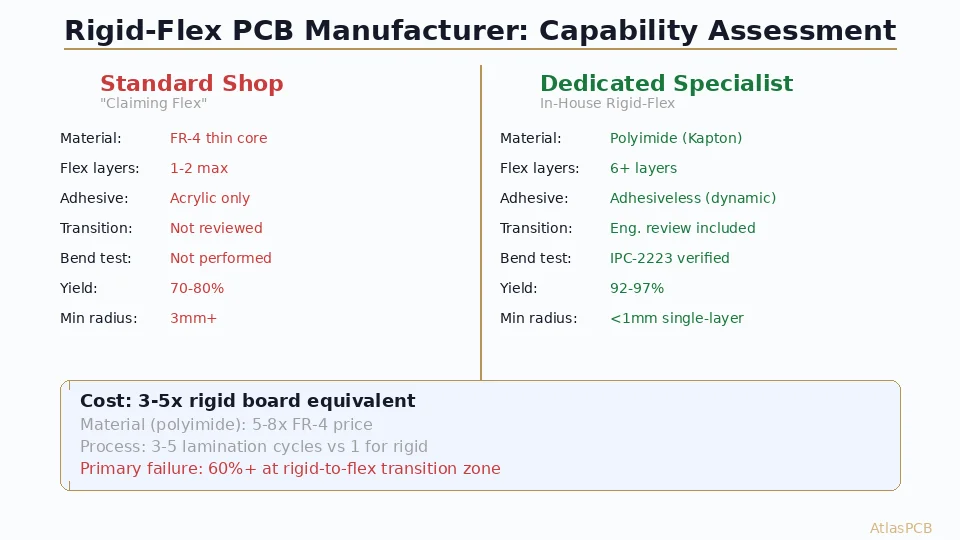
The EV BMS application combines several of the most demanding PCB manufacturing challenges into a single product: rigid-flex construction, heavy copper, high-voltage isolation, and automotive reliability qualification. This makes manufacturer selection critical — the technology exists, but few shops possess all required capabilities simultaneously with automotive certification.
Rigid-Flex Architecture for BMS Applications
Why Rigid-Flex Is Mandatory, Not Optional
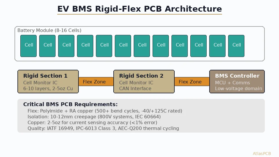
A modern EV battery pack contains 96-108 cells (for 400V systems) or 192-216 cells (800V), organized into modules of 8-16 cells each. Each module requires a cell monitoring circuit that connects to the pack-level BMS controller. Traditional approaches using flex cables or wire harnesses with connectors introduce failure points that automotive reliability standards explicitly discourage.
In our experience fabricating BMS rigid-flex assemblies for Tier 1 automotive suppliers, the typical architecture uses 3-6 rigid sections connected by 2-4 flex zones. Each rigid section hosts the cell monitoring IC (typically Texas Instruments BQ series or Analog Devices ADBMS series) with its associated passive components, while the flex zones traverse between modules, following the physical geometry of the battery pack structure.
The flex zones must accommodate both static bends (installed geometry, typically 90-180 degree bends at fixed radii) and dynamic flex during assembly (the board is flat during SMT, then bent into final configuration during pack assembly). This dual requirement dictates material selection: polyimide base film rated for minimum 500 bend cycles at the installed bend radius, with adhesiveless copper lamination for reliability above 100C.
Layer Stack Architecture
A typical BMS rigid-flex stackup includes:
Rigid sections (6-10 layers): L1 component mounting (2oz Cu), L2 ground plane, L3-4 CAN bus and digital routing, L5-6 power planes (3-5oz Cu), L7-8 additional routing, plus flex layers passing through.
Flex zones (2-4 layers): Polyimide substrate with rolled annealed copper (better fatigue life than electrodeposited), typically 1/2oz or 1oz, carrying cell voltage sense lines and CAN bus differential pairs between rigid sections.
The critical design constraint: flex layers that pass through rigid sections must maintain consistent impedance where they transition between rigid and flex zones. Our process engineers achieve this by maintaining the same dielectric thickness above and below the flex copper through both zones — the rigid section adds structural FR-4 layers around the flex core without altering the flex copper’s electromagnetic environment.
RIGID-FLEX PCB MANUFACTURER
Automotive Rigid-Flex with IATF 16949 Compliance
We produce rigid-flex assemblies up to 22 layers with heavy copper, polyimide flex, and full automotive quality documentation. IST-qualified via structures standard.
High-Voltage Isolation Design on PCB
Creepage and Clearance: The Space Tax
800V BMS systems create a fundamental PCB design challenge: maintaining adequate creepage distance between the high-voltage cell monitoring domain and the low-voltage CAN bus/microcontroller domain. IEC 60664-1 and IPC-2221B provide the baseline requirements, but automotive OEMs typically add 25-50% margin above standards.
For an 800V system with 1000V working voltage (including transients), the minimum creepage at Pollution Degree 2 on a PCB surface (material group IIIa for FR-4) is approximately 8mm. Practically, automotive Tier 1 suppliers specify 10-12mm between voltage domains. This translates to significant keep-out zones on the PCB — a 12mm isolation barrier consumes substantial routing real estate on boards that are already area-constrained.
Manufacturing implications: the isolation barriers often require routed slots (milled channels) through the PCB to physically interrupt the surface creepage path. These slots reduce the effective creepage distance to clearance distance (through-air), allowing tighter physical spacing. However, slotting creates mechanical stress concentration points that interact poorly with thermal cycling — our process engineers reinforce slot terminations with radiused ends (minimum 0.5mm radius) to prevent crack propagation under thermal stress.
Conformal Coating Interaction
Many BMS designs specify conformal coating to reduce effective Pollution Degree (from PD2 to PD1 with coating), which allows reduced creepage distances. However, the rigid-flex transition zones present a coating challenge: conformal coating applied to flex zones can crack during bending, defeating its purpose. Our recommendation: design flex zones to carry only signals within the same voltage domain, keeping high-voltage isolation entirely within rigid sections where conformal coating integrity is maintained.
Material Selection for Automotive Reliability
Flex Zone Materials
The polyimide film selection for automotive BMS flex zones requires attention beyond standard consumer electronics rigid-flex. Key requirements:
Rolled annealed (RA) copper outperforms electrodeposited (ED) copper for fatigue life by a factor of 5-10x at the same thickness. While ED copper fails at 50-100 bend cycles (typical consumer flexible circuit), RA copper survives 500-2000 cycles at the same bend radius. For a BMS application that sees thermal cycling-induced flexure throughout vehicle life, RA copper is non-negotiable.
Adhesiveless construction (directly bonded copper to polyimide) eliminates the weakest link in flex circuits: the adhesive layer. Standard acrylic adhesives soften above 80C and degrade above 105C, making them unsuitable for automotive temperature ranges. Adhesiveless polyimide/copper laminates (DuPont Pyralux AP, Panasonic Felios) maintain bond strength through the full -40 to +125C automotive range without degradation.
Cover layer vs. photoimageable coverlay: For BMS flex zones, liquid photoimageable (LPI) coverlay provides tighter registration on fine-pitch features, but traditional adhesive-bonded polyimide coverfilm offers better chemical resistance and longer-term reliability. Most automotive BMS designs use bonded coverfilm with punched openings for any exposed pads in flex zones.
Rigid Zone Materials
High-Tg FR-4 (Tg 170-180, Td 340+) is the standard choice for BMS rigid sections. The elevated Tg provides margin against the multiple lamination cycles required for rigid-flex construction (each cycle subjects the material to 190-200C for 60-90 minutes) and against the thermal cycling exposure during vehicle life.
For 800V systems requiring additional dielectric strength, some designers specify high-CTI (Comparative Tracking Index) materials rated CTI 600 versus standard FR-4’s CTI 175-250. Higher CTI reduces the likelihood of carbonized tracking paths forming between high-voltage conductors under humidity and contamination exposure.
AUTOMOTIVE PCB SPECIALIST
PCB for EV, ADAS, and Powertrain Applications
Heavy copper, controlled impedance for CAN/CAN-FD, rigid-flex construction, and IATF 16949 quality system. We supply Tier 1 automotive electronics manufacturers.
Get Automotive PCB Quote ›Heavy Copper for Current Sensing Accuracy
BMS designs typically carry two types of current paths: high-current bus connections (50-200A pack current) and precision sense traces (microamp-level measurement signals). The PCB copper weight must satisfy both extremes.
For high-current paths that carry charge/discharge current between cells and the pack terminals, 3-5oz copper (105-175μm) provides the necessary current capacity and thermal dissipation. A 5oz copper trace at 10mm width carries approximately 50A with a 20C temperature rise — adequate for module-level current paths in most passenger vehicle BMS designs.
The precision sensing application demands copper weight from a different perspective: resistance stability. A 1oz copper trace changes resistance by 0.39% per degree C (copper temperature coefficient). For state-of-charge algorithms requiring current measurement accuracy better than 1%, the trace resistance must remain stable. Heavier copper (2oz minimum for sense traces) provides lower absolute resistance, meaning the absolute resistance change per degree C is smaller relative to the shunt resistor value being measured.
In our BMS board production, we commonly use mixed copper weights within the same rigid-flex stackup: 3-5oz on power layers, 2oz on sense layers, and 1/2oz on flex layers. This mixed construction requires careful process control during etching — heavy copper layers need different etch timing than thin copper layers processed in the same panel. Our process uses separate etch passes for different copper weights rather than trying to over-etch thin copper to match heavy copper timing.
Qualification and Testing Requirements
IPC-6013 Class 3 for Rigid-Flex
BMS rigid-flex boards must meet IPC-6013 Type 4 (rigid-flex), Class 3 (high reliability). Key test requirements include: IST (Interconnect Stress Testing) per IPC-TM-650 2.6.26 demonstrating less than 10% resistance change after 150 thermal cycles, peel strength testing at flex/rigid transitions, and bend testing at minimum bend radius for specified cycle count.
Automotive-Specific Qualification
Beyond IPC standards, automotive OEMs require: PPAP documentation (Production Part Approval Process) demonstrating process capability (Cpk > 1.67 for critical dimensions), ongoing reliability testing per AEC-Q200 stress test conditions, full material traceability from copper foil lot to finished board, and periodic cross-section analysis confirming via fill quality and layer registration.
PCB MANUFACTURER FOR AEROSPACE AND AUTOMOTIVE
IPC Class 3 Rigid-Flex with Full Traceability
IATF 16949 quality system, IST qualification, PPAP capability, and lot-level material traceability for automotive BMS, ADAS, and powertrain PCB applications.
View Certifications ›Design-for-Manufacturing Checklist: BMS Rigid-Flex
Before sending your BMS rigid-flex design to manufacturing, verify these critical items that we commonly flag during DFM review:
Bend zone routing: Traces in flex zones must run perpendicular to the bend axis. Traces parallel to the bend axis experience tensile stress on the outer radius and compressive stress on the inner radius, leading to fatigue cracking within 100-200 cycles. Route all flex traces at 90 degrees to the fold line, with smooth curves rather than right-angle turns.
Copper distribution in bend zones: Avoid placing traces only on one side of the flex neutral axis. Asymmetric copper creates a bimetallic-strip effect during temperature changes, inducing unwanted curling. Distribute routing symmetrically across flex layers (top and bottom) or use balanced ground planes on both sides of the flex core.
Transition zone stiffeners: The rigid-to-flex transition is the highest-stress region. Taper the rigid laminate with a 2-3mm chamfer rather than an abrupt edge, and add a polyimide stiffener extending 3-5mm into the flex zone to distribute stress gradients. Without this, we see delamination failures at transitions within 200 thermal cycles.
High-voltage slot termination: All isolation slots must terminate with minimum 0.5mm radius (we recommend 1.0mm). Square-ended slots create stress concentration factors of 3-5x that propagate cracks under thermal cycling. This is one of the most common DFM issues we flag on BMS designs.
ATLASPCB
Building an EV BMS? Start with the Right PCB Partner
From prototype through production qualification, we handle the full BMS rigid-flex lifecycle — DFM review, material qualification, IST testing, and PPAP documentation.
Start Your BMS Project ›Reviewed by AtlasPCB Engineering Team — 15+ years in advanced PCB fabrication for RF, HDI, and rigid-flex applications.
Related Reading:
About AtlasPCB — We specialize in complex PCB manufacturing for HDI, RF, and high-reliability applications. Explore our rigid-flex PCB manufacturing . Every order includes free engineering review. Get your quote.
Reviewed by AtlasPCB Engineering Team — IPC-certified manufacturing specialists with 15+ years of production experience in HDI, RF, and high-reliability PCB fabrication. Content based on factory floor data and real customer design reviews.
- EV BMS PCB
- rigid-flex PCB
- automotive PCB
- battery management system
- rigid-flex PCB manufacturer
- PCB for automotive