· AtlasPCB Engineering · Engineering · 9 min read
Rogers PCB Fabrication: Material Sourcing, Lead Times & Quality Control
What engineers need to know about Rogers PCB fabrication — material sourcing verification, processing requirements for thermoset vs PTFE, hybrid construction, quality control, and how to avoid common fabrication failures.
Rogers laminates are not FR4 — and fabricating them correctly requires different processes, different quality controls, and different supply chain management than standard PCB manufacturing.
This guide covers the practical aspects of Rogers PCB fabrication from the manufacturer’s perspective: what goes right, what goes wrong, and what you should verify as the customer.
Rogers Material Families: Processing Differences
Not all Rogers materials are the same. The fabrication requirements depend on the resin system:
Thermoset Rogers (4000 Series)
Materials: Rogers 4003C, 4350B, 4835
Processing: Similar to FR4
- Standard mechanical drilling — no special drill parameters needed
- Chemical desmear — standard potassium permanganate process works
- Standard electroless copper + electrolytic copper plating
- Compatible with FR4 prepreg in hybrid stackups
- Standard lamination press parameters (similar to FR4)
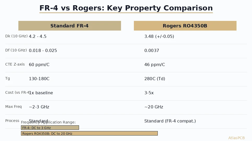
This is the easy Rogers to fabricate. Any manufacturer that handles FR4 can theoretically handle 4003C/4350B with minor process adjustments. The critical difference is impedance modeling (must use Rogers-specific Dk values, not generic FR4 values).
PTFE Rogers (RT/duroid, 5880)
Materials: Rogers 5880, 5870, RT/duroid 6002, 6010
Processing: Specialized — fundamentally different from FR4
- Sodium etch required — PTFE surface is chemically inert. Without sodium etch (sodium-naphthalene complex), copper will not adhere to the PTFE surface. This is a process step that FR4 shops do not have.
- Plasma desmear — Chemical desmear does not work on PTFE. Plasma treatment (oxygen/CF4 gas mixture) is required to clean drill holes.
- Pre-bake mandatory — PTFE absorbs moisture. Boards must be baked at 105-120°C for 2-4 hours before lamination to prevent delamination from steam pressure.
- Modified press cycle — Lower pressure than FR4 (PTFE is soft, over-pressing crushes the dielectric and changes Dk). Different temperature ramp rates.
- Special bondply — FR4 prepreg does not bond to PTFE. Requires FEP or PTFE bondply (Rogers 2929, or Taconic FastRise).
If a manufacturer says they can handle Rogers 5880 but does not have sodium etch equipment, they cannot.
RO3000 Series (Ceramic-filled PTFE)
Materials: Rogers 3003, 3006, 3010, 3035
Processing: Between thermoset and pure PTFE
- Ceramic filling improves processability over pure PTFE
- Still requires sodium etch for plating adhesion
- Drilling is easier than 5880 (ceramic provides mechanical support)
- Used for specific Dk values not available in the 4000 series
Material Sourcing: The Supply Chain Reality
The Sourcing Problem
Rogers Corporation manufactures in the USA and sells globally through distributors. Material availability depends on:
- Your manufacturer’s purchasing relationship — Does the factory buy directly from Rogers or through a distributor?
- Stocking status — Does the factory maintain inventory of your specified type and thickness?
- Lot size economics — Rogers minimum order quantities from the factory are larger than most prototype orders. Small shops may not maintain diverse inventory.
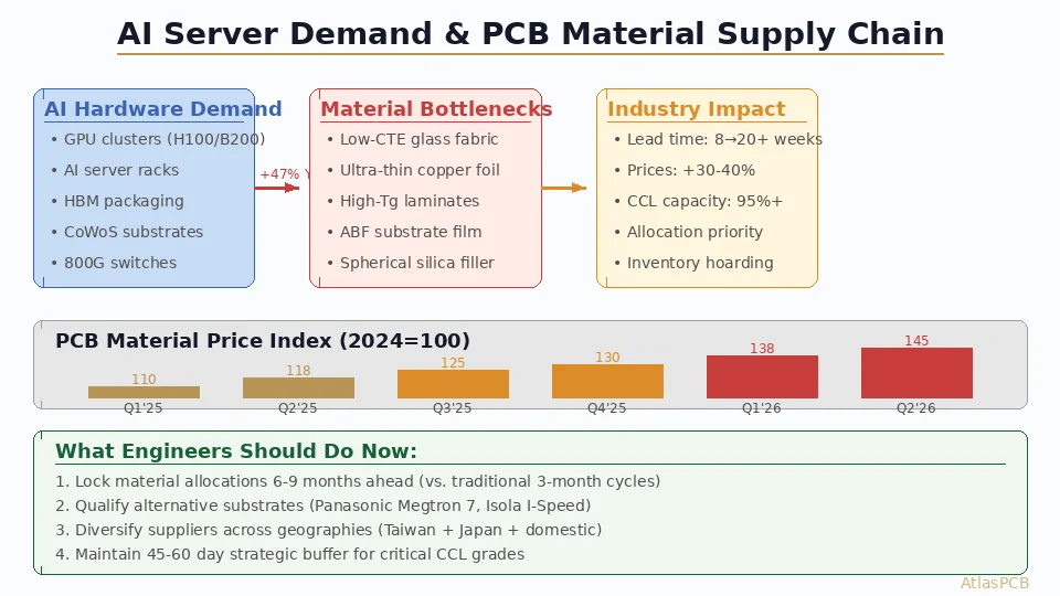
Typical Lead Times
| Scenario | Lead Time |
|---|---|
| Manufacturer stocks the exact type and thickness | Add 0 days — use from inventory |
| Manufacturer stocks the type but not the thickness | 1-2 weeks to source from distributor |
| Material not stocked, standard Rogers product | 2-4 weeks from Rogers/distributor |
| Specialty material (uncommon Dk, unusual thickness) | 4-8 weeks |
Practical impact: A Rogers PCB prototype that should take 2 weeks becomes a 5-week job if material must be sourced. This is the single biggest lead time variable for RF boards.
Material Verification
Material substitution risk is real for expensive laminates. A 20mil sheet of Rogers 4350B costs 8-12x more than equivalent FR4. The economic incentive to substitute exists.
How to verify:
- Certificate of Conformance (CoC) — Every Rogers shipment includes a CoC from Rogers Corporation. Request this with your boards. It lists material type, Dk, lot number, and date.
- Manufacturer’s CoC — The PCB manufacturer’s outgoing CoC should reference the Rogers lot number used.
- Material label photo — For first orders, request photos of the Rogers material labels before processing. Rogers laminates have distinctive branded protective film.
- Electrical verification — If you have TDR equipment, measure impedance on a known trace geometry. If impedance does not match the expected value for the specified Rogers material, something is wrong.
Hybrid Stackup Fabrication
Most Rogers PCBs use hybrid construction — Rogers for RF signal layers, FR4 for everything else.
Thermoset Hybrid (Rogers 4003C/4350B + FR4)
Fabrication considerations:
| Step | Approach |
|---|---|
| Inner layer processing | FR4 inner layers processed normally |
| Stackup assembly | Rogers sheets placed on outer layers, FR4 prepreg between |
| Bondply | Rogers 4450F recommended at Rogers-to-FR4 interface (optional for 4003C — it bonds to FR4 prepreg directly, but 4450F improves adhesion) |
| Lamination | Standard FR4 press cycle works (4003C/4350B cure temperature is compatible) |
| Drilling | Standard mechanical drill — Rogers 4003C drills like FR4 |
| Desmear | Standard chemical desmear |
| Plating | Standard process |
Advantage: Thermoset Rogers hybrid fabrication is straightforward. The main risk is impedance error from using wrong Dk values.
PTFE Hybrid (Rogers 5880 + FR4)
Fabrication considerations:
| Step | Challenge | Solution |
|---|---|---|
| Bondply at interface | FR4 prepreg does not bond to PTFE | FEP bondply (Rogers 2929) or PTFE-compatible adhesive |
| Lamination | Different cure profiles for PTFE and FR4 | Carefully designed temperature/pressure profile |
| CTE mismatch | 5880 z-CTE (237 ppm/°C) vs FR4 (50-70 ppm/°C) | Via reliability testing, conservative aspect ratios |
| Sodium etch | Cannot apply to entire board (damages FR4) | Selective treatment of PTFE surfaces only |
| Press pressure | 5880 requires low pressure; FR4 prepreg needs higher pressure | Compromise profile, often requiring engineering trials |
PTFE hybrid fabrication is genuinely difficult. The manufacturer must have experience with the specific material combination. Ask for reference boards using the same hybrid construction.
Quality Control for Rogers PCBs
Incoming Material Inspection
| Check | Method | Acceptance |
|---|---|---|
| Material type verification | CoC review, label check | Matches order specification |
| Thickness measurement | Micrometer, 5 points per sheet | Within Rogers specification |
| Visual inspection | Backlight inspection for inclusions | No voids, foreign material, or damage |
| Moisture check (PTFE only) | Weigh before and after bake | Weight loss indicates moisture |
In-Process Quality Control
| Process Step | Control |
|---|---|
| Lamination | Thermocouple monitoring of actual temperature profile |
| Drilling | First-hole inspection for hole quality on Rogers material |
| Desmear (PTFE) | Plasma treatment parameter verification |
| Plating | Peel strength test on PTFE surfaces (target ≥4 lb/in per IPC-TM-650) |
| Etching | Trace width measurement on test coupons |
Final Verification
| Test | Requirement |
|---|---|
| Impedance (TDR) | ±5% of target, using frequency-correct Dk |
| Visual inspection | Per IPC-A-600, applicable class |
| Dimensional | Hole locations, board outline per drawing |
| Material CoC | Rogers CoC + manufacturer CoC in shipping package |
Common Rogers Fabrication Failures
Failure 1: Impedance Offset
Symptom: All impedance measurements consistently high or low by 3-5%. Root cause: Manufacturer used generic FR4 Dk (4.2) instead of Rogers-specific Dk (3.38 for 4003C) for impedance calculation. Prevention: Verify the Dk value in the manufacturer’s stackup calculation. It should match the Rogers datasheet at your operating frequency.
Failure 2: Plating Delamination on PTFE
Symptom: Copper peels from the laminate surface during processing or in the field. Root cause: Inadequate or missing sodium etch treatment on PTFE surfaces. Prevention: Confirm PTFE processing capability (sodium etch + plasma desmear) before ordering.
Failure 3: Dielectric Thickness Variation in PTFE
Symptom: Impedance varies across the panel or between boards. Root cause: PTFE material compressed unevenly during lamination due to excessive or uneven press pressure. Prevention: Modified press profile with lower pressure and uniform distribution. Experienced PTFE manufacturers calibrate this for each material type.
Failure 4: Delamination at Hybrid Interface
Symptom: Separation between Rogers and FR4 layers, visible as blisters after thermal stress. Root cause: Inadequate bonding at the material interface — wrong bondply, insufficient temperature, or moisture in PTFE layer. Prevention: Proper bondply selection, pre-bake for PTFE, and lamination profile validation on test panels.
Failure 5: Material Substitution
Symptom: Electrical performance does not match simulation. Impedance or loss is significantly different from expected. Root cause: Different material used than specified — either intentional substitution or supply chain error. Prevention: Require Rogers CoC with every shipment. Verify material type and lot number.
How Atlas PCB Handles Rogers Fabrication
Atlas PCB maintains Rogers laminate inventory and partners with manufacturers experienced in RF PCB fabrication:
- Stocked materials: Rogers 4003C (10/20/30/60 mil), 4350B (10/20/30/60 mil), 5880 (10/20/31/62 mil), Taconic TLY-5 (10/20/31/62 mil)
- PTFE processing: Full sodium etch, plasma desmear, and modified press cycles
- Hybrid expertise: Proven Rogers+FR4 hybrid stackups with validated bondply (Rogers 4450F for thermoset, Rogers 2929 for PTFE)
- Impedance: ±5% with frequency-correct Dk modeling and TDR verification
- Material traceability: Rogers CoC provided with every shipment — material type, lot number, Dk verified
- Lead time: 10-15 working days for stocked materials; we carry the inventory risk
Every Rogers order includes 12-hour engineering pre-audit covering material-specific stackup verification, impedance modeling at operating frequency, hybrid interface compatibility, and PTFE processing requirements.
Frequently Asked Questions
How long does it take to fabricate a Rogers PCB?
Prototype lead time is 10-15 working days when the manufacturer stocks your specified material type and thickness. If material must be sourced, add 2-3 weeks. Rogers 4003C and 4350B in standard thicknesses (10, 20, 30, 60 mil) are most commonly stocked. PTFE materials (5880) have longer sourcing times due to lower demand and higher minimum order quantities.
How do I verify that my manufacturer is using genuine Rogers material?
Request a Rogers Corporation Certificate of Conformance (CoC) with every shipment. The CoC lists material type, thickness, Dk, lot number, and date of manufacture. Verify the manufacturer’s name as purchaser. For first orders, ask for photographs of Rogers material labels before processing. Additionally, compare TDR impedance measurements against expected values calculated with Rogers-specific Dk — significant deviation suggests material substitution.
What is the difference between fabricating Rogers 4003C and Rogers 5880?
Rogers 4003C (thermoset) processes like FR4: standard drilling, chemical desmear, standard plating, and compatible with FR4 prepreg. Rogers 5880 (PTFE) requires specialized processing: sodium etch for copper adhesion, plasma desmear, modified press cycles, pre-baking, and special PTFE bondply for hybrid construction. A manufacturer experienced with 4003C may not be equipped for 5880. Always confirm PTFE-specific capabilities (sodium etch and plasma desmear) before ordering 5880 or any PTFE-based Rogers material.
Summary
- Rogers thermoset (4003C, 4350B) processes like FR4 — straightforward for most manufacturers
- Rogers PTFE (5880, RT/duroid) requires sodium etch, plasma desmear, and modified lamination — verify capability
- Material sourcing is the biggest lead time variable — confirm stocking before committing schedule
- Verify material with Rogers CoC on every shipment — substitution risk exists for expensive laminates
- Hybrid stackups reduce cost but require proper bondply and lamination profile
- Impedance must use Rogers-specific Dk at operating frequency — never use generic FR4 values
Need Rogers PCBs from a manufacturer that stocks the material? Upload your Gerbers for a free engineering review — we verify material availability, hybrid stackup compatibility, and impedance accuracy before production.
Related guides: [RF PCB Manufacturer]/blog/rf-pcb-manufacturer/) | [Rogers 4350B vs FR4]/blog/rogers-4350b-vs-fr4/) | [PCB Materials Guide]/blog/pcb-materials-guide/)
Further Reading
[Rogers 4003C Material Properties: Dk, Df, and Design Considerations]/blog/rogers-4003c-properties/)
[Taconic TLY-5 PCB: Properties, Applications, and Manufacturing Tips]/blog/taconic-tly-5-pcb/)
[PCB Manufacturer with Engineering Review: Why Human DFM Audit Matters]/blog/pcb-manufacturer-engineering-review/)
[RF PCB Materials Comparison: FR4 vs Rogers vs Taconic vs Isola]/blog/rf-pcb-materials-comparison/)
[HDI PCB Design Guide: Stackup Rules, Via Structures & DFM Checklist]/blog/hdi-pcb-design-guide/)
[PCB DFM Checklist: 50 Points to Review Before Sending Gerbers]/blog/pcb-dfm-checklist/)
About AtlasPCB — We specialize in complex PCB manufacturing for HDI, RF, and high-reliability applications. Explore our RF and high-frequency PCB services . Every order includes free engineering review. Get your quote.
Reviewed by AtlasPCB Engineering Team — IPC-certified manufacturing specialists with 15+ years of production experience in HDI, RF, and high-reliability PCB fabrication. Content based on factory floor data and real customer design reviews.
- Rogers PCB
- RF fabrication
- material sourcing
- PTFE processing
- hybrid pcb