· AtlasPCB Engineering · Engineering · 5 min read
Rogers 4350B Stackup Design for 77 GHz Automotive Radar: 6-Layer Hybrid Configuration Guide
Complete stackup design guide for 77 GHz automotive radar PCBs using Rogers 4350B in a hybrid FR-4 configuration. Covers layer assignment, prepreg selection, impedance targets, and manufacturing constraints specific to ADAS radar modules.
Overview: Why 77 GHz Radar Needs a Specialized Stackup
Automotive radar operating at 76-81 GHz pushes PCB fabrication to its limits. At these frequencies, a microstrip patch antenna element on Rogers RO4350B is approximately 1.2mm x 1.2mm — smaller than a standard 0402 passive component pad. Any dimensional error directly shifts resonant frequency and disrupts the array pattern.
This guide provides a production-validated 6-layer hybrid stackup configuration for 77 GHz short-range radar modules, optimized for the balance between RF performance, manufacturing yield, and cost.
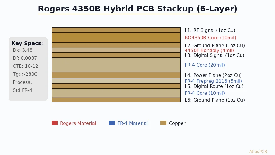
Recommended 6-Layer Hybrid Stackup
| Layer | Material | Thickness | Copper | Function |
|---|---|---|---|---|
| L1 | Rogers RO4350B | 5 mil (0.127mm) | 0.5 oz HTE | Antenna patch array |
| Core 1 | RO4350B | — | — | Antenna substrate |
| L2 | — | — | 1.0 oz | Ground plane / reflector |
| Bond | Rogers 4450F | 4 mil (0.1mm) | — | CTE-managed transition |
| L3 | — | — | 0.5 oz | Corporate feed network |
| Core 2 | FR-4 (Tg170) | 10 mil (0.254mm) | — | Digital/power substrate |
| L4 | — | — | 1.0 oz | MMIC digital interface |
| Prepreg | 2116 FR-4 | 5 mil | — | Standard lamination |
| L5 | — | — | 1.0 oz | Power plane (VCC) |
| Core 3 | FR-4 (Tg170) | 10 mil (0.254mm) | — | Power substrate |
| L6 | — | — | 1.0 oz | Connector/ground |
Layer Assignment Rationale
L1 (Antenna patches): RO4350B with 5-mil thickness minimizes surface wave excitation at 77 GHz while providing adequate bandwidth (~3 GHz) for the 76-81 GHz automotive band. Use HVLP (Hyper Very Low Profile) copper with Rz < 2 microns to minimize conductor loss at this frequency.
L2 (Ground plane): Solid ground immediately below the antenna patches acts as the reflector, setting antenna element gain and controlling back-radiation. No routing permitted — 100% copper fill with via stitching at lambda/10 spacing (0.4mm) around the array perimeter.
L3 (Feed network): The corporate feed network distributes RF signal to all array elements with equal phase and amplitude. This layer runs on the same RO4350B material, separated from L2 by the 4450F bonding layer. Wilkinson dividers, corporate feed trees, and phase-shifter elements are routed here.
L4-L6 (Digital/Power): Standard Tg170 FR-4 handles the MMIC baseband interface (SPI, LVDS data outputs), power supply decoupling, and board-to-board connector routing. No RF-critical signals on these layers.
Critical Manufacturing Specifications
Etch Tolerance
At 77 GHz on RO4350B (Dk 3.48, 5-mil substrate), a patch element is approximately 1.2 x 1.2mm. The resonant frequency sensitivity to dimensional error:
Frequency shift ≈ (Δw/w) × f₀
A +/-0.5 mil (12.5μm) dimensional error on a 1.2mm patch = +/-1.04% → +/-800 MHz frequency shift. This keeps the element within the 76-81 GHz radar band even with worst-case etch variation.
At +/-1.0 mil (standard capability), the frequency shift doubles to +/-1.6 GHz — potentially pushing the antenna response outside the band. This is why 77 GHz radar PCBs require fine-line etch capability.
Specification for fab drawing: “Etch tolerance on Layer 1: +/-0.5 mil (12.5μm). Modified fine-line DES process required. AOI dimensional verification on every panel.”
Material Tolerance
Dk variation directly affects impedance and patch resonance:
- Dk specification: 3.48 +/-0.05 (per IPC-TM-650 2.5.5.5 at 10 GHz)
- Thickness specification: 5.0 mil +/-0.3 mil (6% tolerance)
- Panel-to-panel Dk variation: max 1.5%
Specify on fab drawing: “Rogers RO4350B-LoPro (HVLP copper), 5 mil core thickness, Dk 3.48 +/-0.05. Fabricator to provide incoming material certification per lot.”
Copper Surface Roughness
Surface roughness impact at 77 GHz is severe. Standard HTE copper (Rz 5-8μm) adds 0.5-1.0 dB/inch additional loss compared to smooth copper (Rz 1.5-2.0μm). For a feed network with 20-30mm total trace length, that difference is 1-2 dB of system-level loss — directly reducing radar range.
Specify: HVLP (Hyper Very Low Profile) copper foil, Rz ≤ 2.0μm per IPC-TM-650 2.2.17.
Lamination Parameters
The Rogers-to-FR-4 transition via 4450F prepreg requires specific press parameters:
- Press temperature: 375°F (190°C)
- Pressure: 300-400 PSI
- Dwell time: 60-90 minutes
- Ramp rate: 3-5°F/minute (controlled to prevent thermal shock to RO4350B)
Impedance Targets
| Signal | Target Z₀ | Tolerance | Layer | Reference |
|---|---|---|---|---|
| 50Ω microstrip (antenna feed) | 50Ω | +/-5% | L3 | L2 (GND) |
| 50Ω patch feed point | 50Ω | N/A (matched via geometry) | L1 | L2 (GND) |
| LVDS differential pair | 100Ω diff | +/-10% | L4 | L5 (PWR) |
Feed network impedance on L3 is the most critical — mismatch at feed junctions directly affects array excitation uniformity and sidelobe levels.
Design for Manufacturability Checklist
📋 77 GHz Radar PCB — DFM Checklist
Before sending your 77 GHz radar design to fabrication, verify these manufacturing-critical specifications against your fab partner's capabilities. Request AtlasPCB's DFM review for radar PCBs →
- Etch tolerance confirmation — Verify fabricator can achieve +/-0.5 mil on RO4350B (not just FR-4)
- HVLP copper availability — Confirm availability of Rz ≤ 2.0μm copper foil on RO4350B cores
- 4450F prepreg processing — Confirm fabricator has validated Rogers 4450F lamination parameters
- Selective surface finish — Specify OSP/immersion silver on antenna elements, ENIG on component pads
- Panel orientation — Specify machine-direction alignment relative to array axis for Dk consistency
- Via backfill — Specify VIPPO (via in pad plated over) for MMIC ground vias to eliminate cavity resonance
- Ground via stitching — Lambda/10 spacing (0.4mm pitch) around array perimeter to suppress surface waves
🏭 Need a Manufacturer for 77 GHz Radar PCBs?
AtlasPCB manufactures hybrid Rogers/FR-4 stackups for automotive radar with validated etch tolerance of +/-0.5 mil and in-house HVLP copper processing. We support prototype through volume production for ADAS radar modules. See our RF/high-frequency capabilities →
Related Reading
About AtlasPCB — We specialize in complex PCB manufacturing for HDI, RF, and high-reliability applications. Explore our RF and high-frequency PCB services, or get an multilayer PCB fabrication up to 30 layers . Every order includes free engineering review. Get your quote.
Reviewed by AtlasPCB Engineering Team — IPC-certified manufacturing specialists with 15+ years of production experience in HDI, RF, and high-reliability PCB fabrication. Content based on factory floor data and real customer design reviews.
- Rogers 4350B stackup
- 77 GHz radar PCB
- automotive radar
- hybrid stackup
- RF PCB design
- ADAS