· AtlasPCB Engineering · Engineering · 4 min read
Rigid vs Flexible PCB: Materials, Applications, and How to Choose
Compare rigid, flexible, and rigid-flex PCBs — understand their materials, construction, bend radius, cost differences, and where each type excels in real-world applications.

Not all PCBs are flat, stiff boards. Flexible and rigid-flex PCBs enable designs that bend, fold, and conform to tight spaces. Understanding the differences between rigid, flex, and rigid-flex PCBs helps you choose the right type for your product.
Rigid PCB
Materials
- Substrate: FR-4 (glass-reinforced epoxy) is the standard. High-Tg FR-4, CEM-1, or CEM-3 for specific applications.
- Copper: Standard electrodeposited (ED) copper foil
- Thickness: 0.4mm to 3.2mm (1.6mm standard)
Characteristics
- Cannot bend or flex after manufacturing
- Excellent mechanical stability and dimensional accuracy
- Well-established manufacturing processes
- Widest range of surface finishes and layer counts available
- Lowest cost per unit area
Applications
- Desktop and server motherboards
- Power supplies and converters
- Industrial control systems
- LED lighting panels
- Consumer electronics (TVs, appliances)
Flexible PCB (FPC)
Materials
- Substrate: Polyimide (PI) film — most commonly DuPont Kapton. Typical thickness: 12.5um, 25um, or 50um. Tg > 300°C, excellent chemical resistance.
- Copper: Rolled annealed (RA) copper is preferred over ED copper for flex applications because of its superior fatigue resistance and grain structure.
- Adhesive: Acrylic or epoxy adhesive bonds copper to polyimide. Adhesiveless (cast) constructions available for thinner, more flexible designs.
- Coverlay: Polyimide coverlay (instead of solder mask) covers and protects the flex circuit.
Characteristics
- Can bend, fold, and twist during installation and/or repeated use
- Very thin and lightweight (total thickness as low as 0.1mm)
- Dynamic flex: withstands millions of bend cycles (e.g., laptop hinges, printer heads)
- Static flex: bent once during installation, then remains in position
- Excellent for 3D packaging — fits irregular enclosure shapes
- Higher cost per unit area than rigid PCBs
Key Design Parameters
Minimum Bend Radius:
- Single-layer flex: 6x the total thickness for dynamic, 3x for static
- Double-layer flex: 12x for dynamic, 6x for static
- Multi-layer flex: 24x for dynamic, 12x for static
Copper Type Matters:
- RA copper: better flex life, finer grain, recommended for dynamic flex
- ED copper: acceptable for static flex applications, lower cost
Applications
- Smartphone internal connections (camera module, display, battery)
- Laptop hinges (display to mainboard connection)
- Wearable devices (smartwatches, fitness trackers)
- Medical devices (hearing aids, pacemaker leads)
- Automotive (airbag sensors, dashboard connections)
- Printers (printhead connections)
- Hard disk drives (read/write head connections)

Rigid-Flex PCB
Structure
Combines rigid sections (FR-4) and flexible sections (polyimide) in a single integrated board. The rigid sections carry components, while the flexible sections serve as built-in interconnects.
Construction
- Flexible layers (polyimide + copper) run continuously through both rigid and flex zones
- Additional rigid layers (FR-4) are laminated only in the rigid zones
- Stiffeners may be added to specific flex areas for connector support
Advantages Over Separate Rigid + FFC/FPC
- Eliminates connectors between rigid and flex sections — reducing failure points
- Higher reliability — no contact resistance degradation over time
- 3D packaging — boards can fold into compact shapes
- Reduced assembly steps — fewer separate components to assemble
- Weight reduction — eliminates cables, connectors, and wire harnesses
Disadvantages
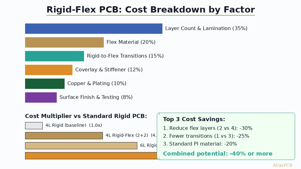
- Higher cost — typically 3-5x the cost of equivalent rigid PCBs
- Longer lead time — 10-20 days typical
- More complex design rules — must account for bend zones, stiffener placement, layer transitions
- Limited supplier base — not all fabricators have rigid-flex capability
Applications
- Military and aerospace (avionics, missile guidance, satellite systems)
- Medical implants (cochlear implants, neurostimulators)
- High-end smartphones and tablets
- Cameras (lens-to-sensor connections)
- Automotive ADAS modules
Comparison Table
| Feature | Rigid | Flexible | Rigid-Flex |
|---|---|---|---|
| Substrate | FR-4 | Polyimide | FR-4 + Polyimide |
| Thickness | 0.4-3.2mm | 0.05-0.5mm | 0.5-3.0mm |
| Bendable | No | Yes | Flex sections only |
| Weight | Standard | Very light | Medium |
| Layer count | 1-30+ | 1-8 | 2-20+ |
| Cost | Low | Medium-High | High |
| Lead time | 2-7 days | 5-10 days | 10-20 days |
| Reliability | Good | Good (if designed properly) | Excellent |
| 3D packaging | No | Yes | Yes |
| Min bend radius | N/A | 3-24x thickness | 6-24x thickness |
Design Tips for Flex and Rigid-Flex
- Route traces perpendicular to the bend axis to minimize stress on copper
- Stagger traces on different layers in multi-layer flex (don’t stack them directly above each other)
- Use curved traces at transition zones — avoid 90-degree bends
- Add teardrops at pad-to-trace junctions to prevent cracking
- Avoid placing vias in bend areas — they create stress concentration points
- Use hatched (crosshatched) ground planes in flex areas instead of solid copper — improves flexibility
- Specify RA copper for any dynamic flex application
- Add stiffeners behind SMD component areas on flex sections for reliable soldering
Cost Factors
| Factor | Impact |
|---|---|
| Layer count | Each additional flex layer adds ~40-50% cost |
| Polyimide type | Adhesiveless (more flexible) costs more |
| Stiffener complexity | FR-4, stainless steel, or polyimide stiffeners |
| Minimum bend radius | Tighter bends require thinner materials |
| Panel utilization | Irregular shapes waste more material |
| Controlled impedance in flex | Requires tighter process controls |
Conclusion
Rigid PCBs remain the workhorse for most electronics. Flexible PCBs shine where bending, folding, or space constraints demand it. Rigid-flex PCBs offer the ultimate in reliability and 3D packaging but at a premium cost. Choose based on your mechanical requirements, reliability needs, and budget — and engage your PCB manufacturer early in the design process for DFM feedback on flex and rigid-flex designs.
Further Reading
[Controlled Impedance PCB: Design, Stackup & Testing Explained]/blog/controlled-impedance-pcb/)
[High-Multilayer FR4 vs Standard FR4: When to Upgrade Material Grade]/blog/high-multilayer-fr4-vs-standard-fr4/)
[PCB DFM Checklist: 50 Points to Review Before Sending Gerbers]/blog/pcb-dfm-checklist/)
[PCB Solder Mask: Types, Colors, and Functions Explained]/blog/pcb-solder-mask-guide/)
[Rigid-Flex PCB Design: Stackup, Bend Rules, and Manufacturing Guidelines]/blog/rigid-flex-pcb-design/)
[IPC Class 3 Requirements: The Complete Guide for Designers]/blog/ipc-class-3-requirements/)
About AtlasPCB — We specialize in complex PCB manufacturing for HDI, RF, and high-reliability applications. Explore our full PCB manufacturing capabilities, or get an instant online quote . Every order includes free engineering review. Get your quote.
Reviewed by AtlasPCB Engineering Team — IPC-certified manufacturing specialists with 15+ years of production experience in HDI, RF, and high-reliability PCB fabrication. Content based on factory floor data and real customer design reviews.
- flexible pcb
- rigid pcb
- flex circuit