· AtlasPCB Engineering · Engineering · 9 min read
Rigid-Flex PCB vs FPC + Board-to-Board Connectors: Making the Right Interconnect Decision
Technical comparison of rigid-flex PCBs versus flexible flat cables with board-to-board connectors. Covers reliability, cost crossover points, assembly yield, and design scenarios where each approach wins.
Quick Decision: Rigid-Flex or FPC + Connectors?
| Factor | Rigid-Flex PCB | FPC + Board-to-Board Connector |
|---|---|---|
| Unit cost (volume 1000+) | $35-65 per interconnect zone | $8-15 per connection (FPC + connector) |
| Prototype cost | $180-500 per panel | $40-80 per panel + $5-15 per FPC |
| Z-height | 0.4-1.0mm at flex zone | 1.5-3.5mm (connector mating height) |
| Vibration resistance | Excellent (no mechanical contacts) | Moderate (contact retention force degrades) |
| Thermal cycle reliability | 50000+ cycles to failure | 2000-8000 cycles (solder joint fatigue) |
| Assembly yield | 99.5%+ (no connector alignment) | 97-99% (FPC insertion defects) |
| Design iteration speed | Slow (full respin required) | Fast (swap FPC length/routing) |
| Impedance control through flex | Yes (microstrip/stripline in flex) | Limited (FPC typically unshielded) |
The one-sentence rule: If your design will see sustained vibration, needs controlled impedance through the flex zone, or must fit under 1.2mm total height at the interconnect, rigid-flex is the right choice. For everything else, FPC + connectors gets you to market faster and cheaper in low volumes.
Understanding the Reliability Gap
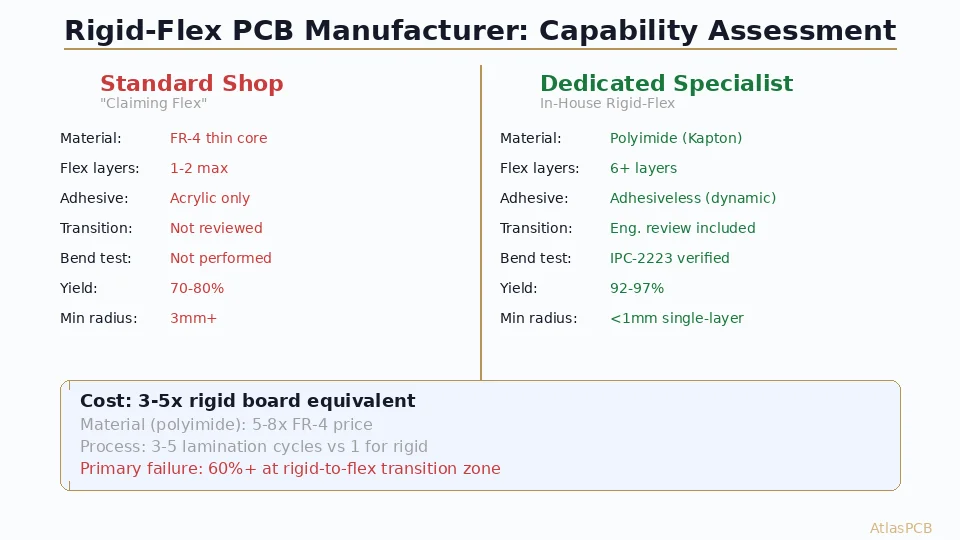
The fundamental reliability advantage of rigid-flex comes from eliminating failure modes rather than managing them. Every board-to-board connector introduces at minimum four potential failure points: two solder joints (one on each board) and two mechanical contact interfaces. In our production facility, we track field return data across customer applications, and connector-related failures consistently account for 35-50% of in-service PCB assembly failures in products exposed to vibration or thermal cycling.
A rigid-flex design replaces those four failure points with continuous copper traces laminated between polyimide dielectric layers. The copper-to-polyimide adhesion (typically 1.0-1.4 N/mm peel strength per IPC-TM-650) far exceeds the mechanical retention force of any ZIF or non-ZIF FPC connector (typically 3-8N total insertion force across all contacts). More importantly, the failure mechanism changes from sudden open-circuit (connector unseating) to gradual fatigue crack propagation in copper, which is both more predictable and much slower to develop.
In our experience running accelerated life testing on rigid-flex assemblies, a properly designed flex zone with single-sided copper routing at 1oz weight and 10:1 bend radius survives 100,000+ dynamic flex cycles before any resistance increase is measurable. The equivalent FPC connector assembly shows measurable contact resistance drift after 2,000-5,000 cycles in the same test fixture.
HIGH-RELIABILITY INTERCONNECTS
Need Rigid-Flex for a Vibration-Critical Application?
Our engineers review your stackup and flex zone design for manufacturability before you commit to tooling. Up to 30-layer rigid-flex with stacked microvias.
Upload Your Design ›Cost Analysis: Where the Crossover Point Lives
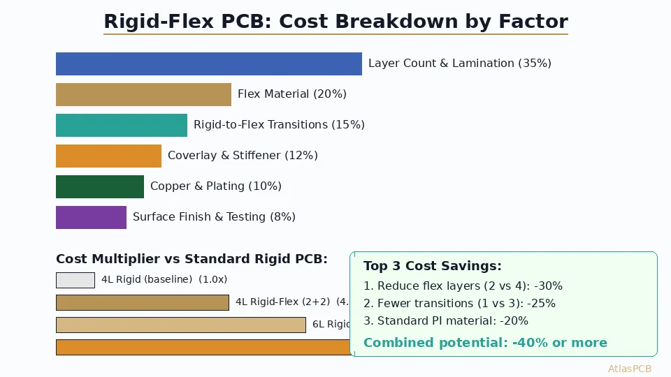
The cost comparison between rigid-flex and FPC+connector approaches is not linear — it depends heavily on volume, complexity, and the specific reliability requirements of your application.
For a typical consumer electronics application with two rigid sections connected by a single flex zone (think: a foldable device hinge or camera module connection), here is how the economics break down:
FPC + Connector Approach (per unit at volume):
- Rigid PCB fabrication: $3-8 per board (two boards)
- FPC cable: $1.50-4.00 (depending on layer count and length)
- Connectors (pair): $0.40-2.50 (ZIF connector on each board)
- Assembly labor (FPC insertion): $0.20-0.50
- Yield loss allocation (1-3% defect rate): $0.15-0.40
- Total per interconnect: $8-18
Rigid-Flex Approach (per unit at volume):
- Rigid-flex fabrication: $35-65 per unit (includes flex zone)
- No additional connectors: $0
- No FPC insertion labor: $0
- Yield loss allocation (0.3-0.5% at flex): $0.10-0.30
- Total per interconnect: $35-65
At first glance, FPC+connectors wins on cost by 3-5x. However, the calculation shifts dramatically when you factor in field failure costs. If your product has a 2% annual connector failure rate and each field repair costs $50-200 (including shipping, labor, and customer goodwill), the total cost of ownership over a 5-year product life often favors rigid-flex for products shipping more than 500-1000 units.
In our facility, we have seen medical device customers switch from FPC+connector to rigid-flex after their first production year, specifically because warranty costs from connector-related failures exceeded the additional fabrication cost within 18 months. The reliability premium pays for itself when failure consequences are high.
Signal Integrity Considerations
For designs carrying high-speed differential pairs (USB 3.x, PCIe, HDMI) through the flex zone, rigid-flex offers a significant advantage that is often overlooked in the cost analysis.
A rigid-flex board maintains controlled impedance through the flex section because you can design the flex layers as proper microstrip or edge-coupled stripline with known dielectric properties. The polyimide dielectric constant (typically 3.2-3.5) and thickness are controlled to the same tolerances as the rigid sections — we hold flex dielectric thickness to +/-10% and achieve impedance tolerance of +/-7% through flex zones.
An FPC cable, by contrast, is typically designed for DC or low-frequency signals. While impedance-controlled FPCs exist, they add significant cost ($5-15 per cable versus $1.50-4 for standard) and still suffer from the impedance discontinuity at the connector interface. The connector itself introduces 1-3nH of parasitic inductance and 0.2-0.5pF of parasitic capacitance per contact, creating reflections that limit usable bandwidth.
For signals above 5 Gbps, we consistently recommend rigid-flex over FPC+connector based on signal integrity simulation results we have validated against TDR measurements in production. The through-flex impedance continuity alone buys you 3-5 dB of margin on your eye diagram.
IMPEDANCE-CONTROLLED FLEX ZONES
High-Speed Signals Through Flex? Get It Right First Time.
We verify impedance continuity through flex zones with pre-production simulation and TDR validation on first articles. Tolerances to +/-7%.
Get Engineering Review ›Assembly and Manufacturing Yield
Assembly yield is an often-underestimated factor in the rigid-flex vs FPC+connector decision. In our conversations with contract manufacturers, FPC connector insertion is consistently cited as one of the top three assembly defect sources, particularly for fine-pitch ZIF connectors (0.3mm and 0.5mm pitch).
Common FPC assembly failure modes include:
- FPC cable inserted at slight angle (2-5% of insertions on 0.3mm pitch)
- Incomplete lock engagement on ZIF actuator
- FPC cable damaged during insertion (cracked conductors at entry point)
- Connector solder joint cracking during reflow (adjacent component heating)
These translate to a typical first-pass yield of 97-99% for FPC connector assemblies versus 99.5%+ for rigid-flex boards (where the flex zone requires no assembly step at all). At volumes of 10,000+ units, that 1-3% yield difference represents significant rework cost and production time.
From the fabrication side, rigid-flex manufacturing yields have improved substantially over the past 5 years. In our facility, we achieve 94-97% first-pass yield on standard rigid-flex designs (4-6 layer, single flex zone) and 88-93% on complex multi-flex-zone designs. These numbers compare favorably to the combined yield of fabricating separate rigid boards plus procuring and qualifying FPC cables and connectors.
When FPC + Connectors Still Wins
Despite the reliability advantages of rigid-flex, there are clear scenarios where the FPC+connector approach remains the better engineering choice:
Serviceability requirements. If your product design requires field-replaceable interconnects (think: printer head cables, laptop display connections), the FPC+connector approach is mandatory. Rigid-flex is permanent — you cannot disconnect and reconnect it without desoldering.
Rapid design iteration. During early prototyping when flex zone routing may change frequently, using FPC+connectors allows you to modify the flexible interconnect without respinning the rigid PCB. This can save 2-3 weeks per iteration cycle.
Ultra-cost-sensitive high-volume consumer electronics. For products shipping 100,000+ units in benign environments (minimal vibration, controlled temperature), the $20-40 per-unit cost difference often cannot be justified by reliability gains. This is why smartphone internal FPC cables remain connector-based despite the Z-height disadvantage.
Multi-vendor assembly. When different subassemblies are manufactured at different facilities and connected during final assembly, connectors provide the necessary mechanical interface. Rigid-flex requires the entire assembly to be fabricated as one piece.
NOT SURE WHICH APPROACH?
Send Us Your Design — We Will Recommend the Best Approach
Our rigid-flex specialists analyze your mechanical constraints, signal requirements, and volume targets to recommend the most cost-effective interconnect strategy.
Get Recommendation ›Decision Framework: A Practical Flowchart
Use this decision sequence to determine your interconnect approach:
- Does the flex zone carry signals above 5 Gbps? If yes, strongly favor rigid-flex for impedance continuity.
- Is Z-height at the interconnect constrained below 1.5mm? If yes, rigid-flex eliminates connector mating height.
- Will the product experience sustained vibration above 3G RMS? If yes, rigid-flex eliminates mechanical contact failure modes.
- Does the product require field serviceability at the interconnect? If yes, FPC+connector is mandatory.
- Is production volume below 200 units? If yes, FPC+connector is almost always more economical for prototyping.
- Is your total product BOM target below $15? If yes, the rigid-flex premium likely exceeds your budget.
For designs that fall in the middle (moderate vibration, moderate volume, moderate speed), the decision often comes down to product lifetime expectations. A 2-year consumer device can tolerate connector wear. A 15-year industrial controller cannot.
ATLASPCB
Ready to Design Your Rigid-Flex or Need a Quote for Both Approaches?
We fabricate both rigid-flex (up to 22 layers) and standard rigid boards with FPC connector footprints. Get comparative pricing in 24 hours.
Get Instant Quote ›Reviewed by AtlasPCB Engineering Team — 15+ years in advanced PCB fabrication for RF, HDI, and rigid-flex applications.
Related Reading:
About AtlasPCB — We specialize in complex PCB manufacturing for HDI, RF, and high-reliability applications. Explore our rigid-flex PCB manufacturing . Every order includes free engineering review. Get your quote.
Reviewed by AtlasPCB Engineering Team — IPC-certified manufacturing specialists with 15+ years of production experience in HDI, RF, and high-reliability PCB fabrication. Content based on factory floor data and real customer design reviews.
- rigid-flex PCB
- FPC
- board-to-board connector
- PCB interconnect
- design decision