· AtlasPCB Engineering · Engineering · 5 min read
PCB Prototyping vs Mass Production: Key Differences and Best Practices
Understand the differences between PCB prototyping and mass production — cost structures, lead times, testing strategies, design considerations, and how to transition smoothly from prototype to volume.

The journey from a PCB prototype to mass production involves significant changes in manufacturing approach, quality requirements, and cost optimization. Understanding these differences helps engineers plan effectively and avoid costly surprises during the transition.
Prototype vs Production: Overview
| Aspect | Prototype | Production |
|---|---|---|
| Quantity | 1-50 pieces | 100-1,000,000+ |
| Priority | Speed and flexibility | Cost and consistency |
| Testing | Functional validation | Statistical quality control |
| Tooling | No tooling cost | Fixtures, stencils, test jigs |
| Lead time | 24 hours - 5 days | 1-4 weeks |
| Unit cost | High ($5-50/board) | Low ($0.50-5/board) |
| Quality standard | IPC Class 1-2 | IPC Class 2-3 |
Prototyping Phase
Goals
- Validate circuit functionality
- Verify component footprints and mechanical fit
- Test thermal performance
- Debug firmware/software integration
- Identify design issues before committing to volume
Typical Prototype Process
- Design review: Engineer self-review or peer review of schematic and layout
- Quick-turn fabrication: 24-72 hour PCB fabrication (2-4 layer typical)
- Manual or small-batch assembly: Hand soldering or small SMT run (5-20 boards)
- Functional testing: Bench testing of key functions
- Iterate: Fix issues, respin board, repeat
Prototype Cost Structure
- Per-board cost is high due to no amortization of setup costs
- NRE (Non-Recurring Engineering) cost is low — no tooling, no fixtures
- Total project cost is low because quantities are small
Best Practices for Prototyping
- Use your manufacturer’s standard stackup and materials to minimize lead time
- Include test points for all critical signals — you’ll need them for debugging
- Use larger component sizes when possible (0805 vs 0402) for easier hand assembly
- Add extra connectors or headers for debug access
- Include version marking on silkscreen (V1.0, date)
- Keep 1-2 spare boards for destructive testing
Production Phase
Goals
- Consistent quality across all units
- Minimum cost per unit
- Reliable supply chain
- Traceability and compliance
- Scalable manufacturing process
Production Process
- DFM/DFA review: Manufacturer reviews design for manufacturability
- First article inspection (FAI): First production boards are fully inspected
- Tooling fabrication: Test fixtures, stencils, programming jigs
- Pilot run: Small production batch (50-100 units) to validate process
- Mass production: Full-volume manufacturing with statistical process control
- Ongoing quality monitoring: SPC charts, yield tracking, defect analysis
Production Cost Structure
- Per-board cost drops dramatically with volume (setup costs amortized)
- NRE cost is significant: Test fixtures ($3K-15K), stencils ($50-300), programming jigs ($500-5K)
- Total project cost is high but cost per unit is low
Panel Optimization
In production, boards are panelized for efficient manufacturing:
- Panel layout optimized for maximum utilization (>80% target)
- V-score or tab routing for depanelization
- Fiducials and tooling holes added for automated assembly
- Bad board marks for selective assembly skipping

Key Differences in Detail
1. Component Sourcing
Prototype: Buy from distributors (Digi-Key, Mouser) — immediate availability, small quantities, higher unit price.
Production: Buy from manufacturers or authorized distributors — longer lead time (8-16 weeks for some ICs), MOQ requirements, lower unit price. Consider alternate/second-source components.
2. Testing Strategy
Prototype: Manual functional testing, oscilloscope probing, visual inspection.
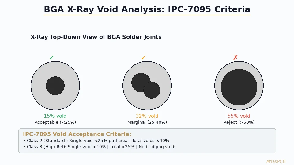
Production: Automated testing pipeline — SPI → AOI → ICT/flying probe → functional test → (X-ray for BGA). Each test method catches different defect types.
3. Quality Documentation
Prototype: Minimal documentation. Maybe a test checklist.
Production: Full documentation — IPC class specification, first article report, certificate of conformance, material certificates, lot traceability, test reports.
4. Design Changes
Prototype: Easy and cheap to change — just respin the board.
Production: Expensive to change — requires new tooling, updated BOM, re-qualification, potential scrap of existing inventory. Use ECO (Engineering Change Order) process.
Transitioning from Prototype to Production
Pre-Production Checklist
- Freeze the design — no more changes after this point
- Complete DFM review with production manufacturer
- Finalize BOM with approved manufacturers and alternates
- Create test specifications for each test stage
- Design test fixtures (ICT, functional test)
- Order production stencils (laser-cut, not chemically etched)
- Establish incoming quality criteria for components
- Define acceptance criteria (IPC class, cosmetic standards)
- Plan pilot run (50-100 units) before full production
- Set up traceability (lot codes, date codes, serial numbers)
Common Pitfalls
- Prototype worked but production fails: Often due to component tolerance stacking — prototype used favorable components, production sees the full tolerance range
- BOM issues: Components used in prototype are obsolete, unavailable, or have long lead times
- Thermal problems at scale: Prototype tested at room temperature; production sees full temperature range
- Assembly yield too low: Design wasn’t optimized for automated assembly (DFA)
Cost Optimization for Production
PCB Fabrication
- Use standard materials and stackups
- Minimize layer count (4-layer vs 6-layer saves 30-40%)
- Optimize panel utilization
- Use standard board thickness (1.6mm)
- Avoid unnecessary features (blind vias, heavy copper, special finishes)
Assembly
- Minimize component count and unique part numbers
- Use common package sizes (0402, 0603 for passives)
- Design for single-side assembly when possible
- Avoid manual operations (hand soldering, manual insertion)
- Standard stencil (not step stencil) when possible
Testing
- Design for testability (DFT) to enable efficient ICT
- Combine test steps where possible
- Automate functional testing with custom test jigs
- Use statistical sampling for mature products
Conclusion
Successful transition from prototype to production requires planning from the design stage. Design with production in mind — follow DFM/DFA guidelines, source production-grade components, and plan your test strategy early. A well-executed pilot run catches process issues before they become expensive production problems. The investment in pre-production planning pays for itself many times over in reduced production costs and higher yields.
Further Reading
[Blind Via vs Buried Via: Design Rules, Cost Impact & When to Use Each]/blog/blind-via-vs-buried-via/)
[PCB DFM Checklist: 50 Points to Review Before Sending Gerbers]/blog/pcb-dfm-checklist/)
[PCB Manufacturing Process: 15 Steps from Gerber to Finished Board]/blog/pcb-manufacturing-process-15-steps/)
[Heavy Copper PCB: Design Rules, Manufacturing Limits, and Thermal Management]/blog/heavy-copper-pcb/)
[PCB Cost Optimization: 15 Practical Ways to Reduce Board Cost]/blog/pcb-cost-optimization/)
[HDI PCB Design Guide: Stackup Rules, Via Structures & DFM Checklist]/blog/hdi-pcb-design-guide/)
[PCB Thermal Management: Heat Dissipation Techniques for Reliable Electronics]/blog/pcb-thermal-management/)
About AtlasPCB — We specialize in complex PCB manufacturing for HDI, RF, and high-reliability applications. Explore our full PCB manufacturing capabilities . Every order includes free engineering review. Get your quote.
Reviewed by AtlasPCB Engineering Team — IPC-certified manufacturing specialists with 15+ years of production experience in HDI, RF, and high-reliability PCB fabrication. Content based on factory floor data and real customer design reviews.
- prototyping
- mass production
- pcb manufacturing
- NPI