· AtlasPCB Engineering · Engineering · 13 min read
Plated Through-Hole Reliability: Barrel Crack Prevention, IPC Testing & Design Rules
Learn how to prevent PTH barrel cracks through proper copper plating thickness, aspect ratio control, and IPC TM-650 testing. Expert design rules for thermally reliable plated through-holes.
Introduction: Why PTH Reliability Matters
Plated through-holes (PTHs) are the backbone of multilayer PCB interconnection. Every via, every component lead hole, and every press-fit connector relies on a thin copper barrel to carry signals and power between layers. When that barrel cracks, the entire circuit fails — often intermittently and almost always in the field, where diagnosis is costly and repair is impractical.
PTH barrel cracking ranks among the top three PCB reliability failure modes alongside conductive anodic filament (CAF) growth and pad cratering. For [IPC Class 3]/blog/ipc-class-3-requirements/) applications — military, aerospace, medical implants, automotive safety systems — barrel crack prevention is not optional. It is a fundamental design and manufacturing requirement.
This article provides a comprehensive engineering guide to PTH reliability, covering the physics of barrel cracking, IPC testing methodologies, design rules that prevent failures, and fabrication controls that ensure consistent plating quality. Whether you are designing a 20-layer backplane or a 4-layer power supply, the principles here will help you specify and verify robust plated through-holes.
The Physics of PTH Barrel Cracking
Z-Axis Thermal Expansion
The root cause of barrel cracking is the mismatch in coefficient of thermal expansion (CTE) between copper and FR-4 laminate along the z-axis:
- Copper CTE: ~17 ppm/°C (isotropic)
- FR-4 z-axis CTE (below Tg): ~50-70 ppm/°C
- FR-4 z-axis CTE (above Tg): ~250-300 ppm/°C
Below the glass transition temperature (Tg), the z-axis expansion of FR-4 is already 3-4× greater than copper. Above Tg (typically 130-180°C depending on resin system), the expansion rate jumps dramatically. During a reflow soldering cycle where peak temperatures reach 245-260°C, the total z-axis expansion of a 2.0 mm thick board can exceed 60 µm — all of which must be absorbed by the copper barrel.
Stress Concentration Points
Barrel cracks do not form randomly. They concentrate at predictable locations:
- Mid-barrel: The point of maximum z-axis displacement, equidistant from the constraining surface copper layers
- Inner-layer interconnects: Where the barrel meets internal copper planes, creating stress risers at the knee (the transition point between barrel and pad)
- Corner cracks: At the junction between the barrel wall and the land area on outer layers
The stress at any point along the barrel is proportional to the distance from the nearest constraining copper layer. This is why thicker boards with higher layer counts are inherently more susceptible to barrel cracking.
Failure Modes
PTH failures manifest in several distinct patterns:
- Barrel fatigue crack: A circumferential crack, typically at mid-barrel, resulting from repeated thermal cycling. This is the most common field failure mode.
- Corner crack: A crack propagating from the outer pad-to-barrel junction, often caused by excessive z-axis stress during reflow.
- Separation at inner layer: Delamination between the barrel copper and the inner-layer pad, caused by poor copper-to-copper bonding or contamination.
- Nail-heading: Lateral copper displacement at inner layers, indicating excessive drilling heat or poor hole preparation.
IPC Testing Methods for PTH Reliability
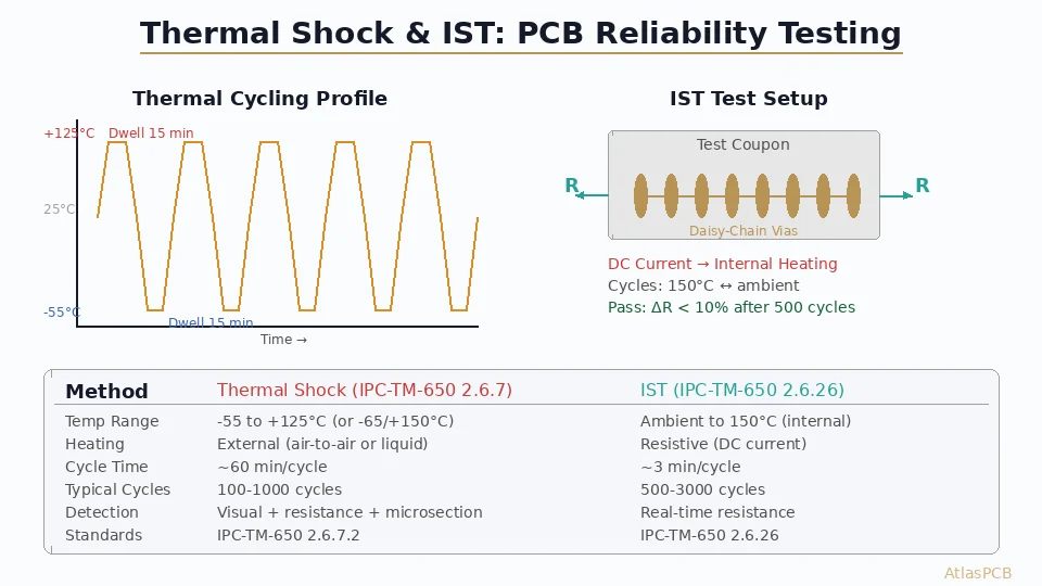
IPC TM-650 Method 2.6.26 — Interconnect Stress Test (IST)
The IST is the gold standard for PTH reliability assessment. It works by:
- Fabricating dedicated test coupons with daisy-chain via patterns alongside production panels
- Applying direct current to heat the coupons from room temperature to 150°C (or 190°C for lead-free assemblies) in approximately 3 minutes
- Allowing air cooling back to ambient temperature
- Continuously monitoring the resistance of the daisy chain
- Defining failure as a >10% resistance increase from baseline
A typical IST qualification requires 500-1,000 cycles without failure. High-reliability programs often specify 2,000+ cycles. The IST directly measures the cumulative damage from thermal cycling in an accelerated timeframe.
IPC TM-650 Method 2.6.8 — Thermal Stress (Solder Float)
This is a pass/fail test where:
- A coupon is conditioned at 125°C for 6 hours
- Floated on molten solder at 288°C for 10 seconds
- Microsectioned and examined for cracks, delamination, or degradation
For Class 3 products, this test is typically performed on every production lot. It is a screening test, not a life prediction tool — it catches gross defects but does not quantify fatigue life.
Microsection Analysis — IPC TM-650 Method 2.1.1
Microsectioning remains the definitive method for measuring:
- Copper plating thickness at minimum, average, and maximum points along the barrel
- Plating uniformity (ratio of minimum to average thickness)
- Etchback and smear removal quality
- Inner-layer connection integrity
- Dielectric thickness between layers
- Wicking or contamination
A proper microsection requires grinding to the hole center (±10% of hole diameter), polishing to a mirror finish, and etching to reveal the copper grain structure. Experienced microsection analysts can identify potential reliability risks — such as columnar grain structure, voids, or inclusions — that will not show up in electrical testing until much later in service life.
Additional Test Methods
- IPC TM-650 Method 2.6.27 — Thermal Cycling: Board-level thermal cycling from -55°C to +125°C (or more aggressive profiles) with resistance monitoring
- IPC TM-650 Method 2.6.7 — Thermal Shock: Rapid temperature transitions to assess extreme stress conditions
- Time-Domain Reflectometry (TDR): Useful for detecting subtle impedance changes caused by incipient cracks in controlled-impedance vias
For a broader overview of PCB testing approaches, see our guide to [PCB testing methods]/blog/pcb-testing-methods/).
Design Rules for Reliable PTH
Aspect Ratio
The aspect ratio of a PTH — defined as board thickness divided by drilled hole diameter — is the single most critical design parameter for barrel reliability:
| Aspect Ratio | Reliability Risk | Typical Application |
|---|---|---|
| <6:1 | Low | Standard commercial products |
| 6:1 – 8:1 | Moderate | Industrial, telecom |
| 8:1 – 10:1 | High | Requires enhanced plating controls |
| 10:1 – 12:1 | Very High | Specialized processes, HDI builds |
| >12:1 | Extreme | Requires advanced plating (PPR, pulse plating) |
Design rule: Keep aspect ratios below 8:1 for standard reliability requirements. For IPC Class 3, many fabricators limit aspect ratio to 10:1 unless pulse-reverse plating and enhanced process controls are in place.
For thick boards where high aspect ratios are unavoidable, consider using [HDI technology]/blog/hdi-pcb-design-guide/) with microvias and stacked via structures to reduce the effective depth each via must span.
Copper Plating Thickness
IPC-6012 specifies the following minimums:
| Class | Average Thickness | Minimum at Any Point |
|---|---|---|
| Class 1 | 20 µm (0.8 mil) | 18 µm (0.7 mil) |
| Class 2 | 20 µm (0.8 mil) | 18 µm (0.7 mil) |
| Class 3 | 25 µm (1.0 mil) | 20 µm (0.8 mil) |
Design rule: For Class 3 applications, specify 25 µm minimum average with an internal target of 30 µm. This provides manufacturing margin and additional copper for fatigue resistance.
Copper plating thickness is intimately connected to the [copper weight and thickness decisions]/blog/pcb-copper-weight-thickness/) on your outer layers, since the same plating bath deposits copper on both surfaces simultaneously.
Hole Size and Drill Quality
- Minimum drill diameter: 0.20 mm (8 mil) for mechanical drilling; below this, consider laser drilling for microvias
- Drill-to-copper clearance: Minimum 0.20 mm (8 mil) annular ring for Class 3 per IPC-6012
- Drill accuracy: ±0.05 mm (2 mil) for standard; ±0.025 mm (1 mil) for HDI
- Drill bit condition: Worn bits generate excessive heat, causing smear and nail-heading. Specify maximum hit counts per IPC-6012.
Pad and Annular Ring Design
The annular ring — the copper ring surrounding the drilled hole — provides the mechanical anchor for the PTH barrel to the internal and external layers:
- IPC Class 3 external annular ring: ≥0.050 mm (2 mil) minimum after plating
- IPC Class 3 internal annular ring: ≥0.025 mm (1 mil) minimum
- Best practice: Design nominal annular ring of 0.15-0.20 mm (6-8 mil) to accommodate drill registration tolerances
Insufficient annular ring leads to breakout conditions where the hole partially misses the pad. Even partial breakout creates a stress concentration that significantly increases the risk of barrel cracking at that layer connection.
Thermal Relief vs. Direct Connection
When a PTH connects to a large copper plane, thermal relief pads are commonly used to improve solderability. However, thermal reliefs also affect PTH reliability:
- Direct connection: Provides maximum mechanical support and heat dissipation but makes hand soldering difficult
- Thermal relief (4-spoke): Standard pattern; provides adequate mechanical support for most applications
- Thermal relief (2-spoke): Reduced mechanical support; avoid for Class 3 applications
- Spoke width: Minimum 0.20 mm (8 mil) for mechanical strength; 0.25 mm (10 mil) preferred
For [thermal management]/blog/pcb-thermal-management/) applications where planes carry significant heat, direct connections are preferred for both thermal and reliability reasons.
Fabrication Controls for PTH Quality
Electroless Copper Deposition
The electroless (autocatalytic) copper layer is the foundation of PTH plating. It provides the conductive seed layer that enables subsequent electrolytic plating. Critical controls include:
- Thickness: 0.5-1.5 µm (20-60 µin) — enough for conductivity, thin enough to avoid brittleness
- Adhesion: Verified by tape pull test; dependent on proper catalyzation and surface preparation
- Coverage: Must coat the entire hole wall uniformly, including the smear-removed resin surface
- Bath chemistry: Formaldehyde-based reducers require tight pH (12.0-13.0), temperature (30-35°C), and copper concentration (2.5-3.0 g/L) control
Desmear and Etchback
After drilling, resin smear from the heat of drilling coats the inner-layer copper surfaces. This smear must be removed to ensure reliable copper-to-copper connections:
- Permanganate desmear: Standard process using alkaline permanganate to oxidize and remove resin
- Plasma desmear: Dry process using oxygen/CF4 plasma; more uniform for high-aspect-ratio holes
- Etchback: Intentional recession of the resin below the inner-layer copper (typically 5-15 µm) to create a three-point connection (barrel-to-pad top, side, and bottom)
IPC Class 3 specifications typically require positive etchback. The additional copper-to-copper contact area significantly improves the shear strength of the inner-layer connection.
Electrolytic Copper Plating
The main barrel plating process determines the thickness, uniformity, and ductility of the copper — all of which directly affect reliability:
- DC acid copper plating: Standard process; adequate for aspect ratios up to ~8:1
- Periodic pulse reverse (PPR) plating: Reverses current periodically to dissolve excess copper from the hole mouth, improving throwing power; essential for aspect ratios above 10:1
- Current density: Typically 1.5-3.0 A/dm²; higher densities risk poor ductility and rough deposits
- Plating time: Calculated based on target thickness and current density; typically 60-90 minutes for 25 µm
- Bath additives: Brighteners, levelers, and carriers must be maintained within tight limits using CVS (Cyclic Voltammetric Stripping) analysis
Throwing power — the ability to deposit copper uniformly throughout the hole depth — is the critical metric. It is measured as the ratio of center-barrel thickness to surface thickness. A throwing power of >80% is considered excellent; <60% indicates a process problem that will produce unreliable vias in high-aspect-ratio holes.
Copper Ductility
Elongation is the measure of copper ductility. IPC-6012 Class 3 requires a minimum elongation of 18% for electrodeposited copper. Low ductility copper (from contaminated baths, excessive current density, or organic co-deposition) will crack under thermal stress even at adequate thickness.
Ductility is tested by plating copper onto a standardized test strip and performing a tensile test per IPC TM-650 Method 2.4.18. Many high-reliability programs specify elongation >20% as an internal standard.
Material Selection Impact on PTH Reliability
Laminate Tg and Z-Axis CTE
The choice of laminate material directly affects PTH reliability through its z-axis CTE:
| Material | Tg (°C) | Z-CTE below Tg (ppm/°C) | Z-CTE above Tg (ppm/°C) |
|---|---|---|---|
| Standard FR-4 | 130-140 | 50-70 | 250-300 |
| Mid-Tg FR-4 | 150-160 | 45-60 | 200-250 |
| High-Tg FR-4 | 170-180 | 40-55 | 180-220 |
| Polyimide | 250+ | 35-50 | 50-80 |
| IS680 / Megtron 6 | 200+ | 30-45 | 60-100 |
Design rule: For boards thicker than 2.0 mm or with aspect ratios above 8:1, use high-Tg (≥170°C) or low-CTE laminate systems. The reduced z-axis expansion directly translates to lower stress on the copper barrel.
For detailed guidance on layer buildup decisions, consult our [PCB stackup calculator]/blog/pcb-stackup-calculator/).
Filler Content
Modern laminate systems use silica fillers to reduce z-axis CTE. Higher filler content (60-70% by weight) provides:
- Lower z-axis CTE
- Improved dimensional stability
- Better drill quality (cleaner hole walls)
- Slightly higher dielectric constant (which must be accounted for in impedance calculations)
Filled resin systems like Panasonic Megtron 6, Isola IS680, and Rogers RO4000 series offer z-axis CTEs as low as 30-40 ppm/°C below Tg, dramatically improving PTH reliability in thick board constructions.
Reliability Prediction and Qualification
Coffin-Manson Fatigue Model
PTH barrel fatigue follows the Coffin-Manson low-cycle fatigue model:
N_f = C × (Δε)^(-n)
Where:
- N_f = cycles to failure
- Δε = strain range per cycle (determined by CTE mismatch and temperature range)
- C, n = material constants for electrodeposited copper (n ≈ 2.0-2.5)
This model predicts that:
- Doubling the strain range reduces fatigue life by 4-6×
- Every 10°C reduction in peak temperature extends life significantly
- Thicker copper (which reduces strain for a given displacement) improves life quadratically
Qualification Testing Strategy
A robust PTH qualification program includes:
- Incoming material verification: Tg, CTE, and time-to-delamination (T-260/T-288) testing on laminate lots
- Process monitoring: Regular microsection analysis (minimum weekly for high-volume) measuring plating thickness, uniformity, and etchback
- IST testing: On coupons from every production lot for Class 3 products
- Solder float testing: Per IPC TM-650 2.6.8 on lot coupons
- Periodic extended IST: Full 2,000-cycle IST quarterly to verify process margin
- Copper ductility testing: Monthly tensile testing of plated copper
For comprehensive fabrication verification including PTH quality, refer to our [DFM checklist]/blog/pcb-dfm-checklist/).
Common PTH Reliability Mistakes
Design Mistakes
- Ignoring aspect ratio in thick boards: A 0.30 mm drill in a 3.2 mm board creates a 10.7:1 aspect ratio — well into the danger zone
- Insufficient annular ring: Designing tight-tolerance annular rings without accounting for drill wander
- Via-in-pad without proper filling: [Via-in-pad]/blog/via-in-pad-design/) designs that are not properly filled and planarized create void entrapment during reflow
- Non-functional pads removed: Removing non-functional pads (NFPs) reduces the constraining effect on the barrel; retain NFPs for Class 3
Manufacturing Mistakes
- Excessive drill hits per bit: Worn drill bits generate heat, causing smear and poor hole quality
- Inadequate desmear: Residual smear prevents copper-to-copper bonding at inner layers
- Plating bath contamination: Organic contaminants reduce copper ductility below IPC minimums
- Poor throwing power: Insufficient leveler concentration causes thin mid-barrel plating
Testing Mistakes
- Testing only on standard coupons: Test coupons should represent the worst-case aspect ratio on the production board
- Insufficient sample size: A minimum of 5 microsection sites per coupon, 3 coupons per lot
- Skipping IST for Class 2 products: Even Class 2 products in harsh environments benefit from IST qualification
Advanced Techniques for Extreme Reliability
Copper-Wrapped Via (Through-Hole Fill with Cap Plating)
For the highest reliability, vias can be filled with conductive or non-conductive paste and then cap-plated with additional copper. This creates a solid copper column that virtually eliminates barrel cracking. This technique is standard in [HDI PCB construction]/blog/hdi-pcb-design-guide/) for stacked microvia builds.
Via-in-Pad Plated Over (VIPPO)
VIPPO combines via filling and planarization with subsequent plating, creating a flat, solderable surface directly over the via. When properly executed, the filled via has superior thermal cycling performance compared to open vias because the fill material supports the barrel against z-axis strain.
Back-Drilled Vias (Stub Removal)
While back-drilling is primarily used for signal integrity in high-speed designs, it also affects reliability by removing the unsupported barrel length below the deepest connected layer, reducing the effective aspect ratio and z-axis stress span.
Conclusion
PTH reliability is not a single-variable problem — it requires coordinated attention to design (aspect ratio, annular ring, material selection), fabrication (plating thickness, uniformity, ductility, desmear), and verification (microsection, IST, solder float testing). The IPC-6012 and IPC TM-650 standards provide a comprehensive framework, but achieving truly reliable plated through-holes requires understanding the physics behind the specifications.
For engineering teams working on high-reliability products, investing in proper PTH qualification pays dividends in field reliability and warranty cost reduction. The cost of IST coupons and microsection analysis is trivial compared to the cost of a single field failure in a safety-critical system.
At Atlas PCB, our engineering team works with customers from the design stage through fabrication qualification to ensure that every plated through-hole meets its reliability requirements — whether the application is consumer electronics or deep-space avionics.
Atlas PCB specializes in high-reliability multilayer PCB fabrication with IPC Class 3 plating controls and comprehensive PTH qualification testing. Contact us for engineering support and a free DFM review on your next project.
Further Reading
- [PCB Design for GaN and SiC Power Devices: Thermal Management, Layout Rules, and Material Selection]/blog/pcb-design-gan-sic-power-devices-thermal-layout/)
- [PCB Via Reliability Testing: IST, Thermal Cycling, and IPC-6012 Compliance for Microvias]/blog/pcb-via-reliability-testing/)
- [AI Hardware PCB Thermal Management: Advanced Multilayer Stackup Design for 1000W+ Processing Units]/blog/ai-hardware-pcb-thermal-management-multilayer-design/)
- [PCB Rigid-Flex Bend Zone Reliability: Design Rules, Material Selection & Lifecycle Testing]/blog/pcb-rigid-flex-bend-zone-reliability/)
- [ENEPIG vs ENIG Surface Finish: Complete Comparison for Wire Bonding, Solderability, and Long-Term Reliability]/blog/enepig-vs-enig-surface-finish-wire-bonding/)
- Our Manufacturing Capabilities
About AtlasPCB — We specialize in complex PCB manufacturing for HDI, RF, and high-reliability applications. Explore our aluminum and metal-core PCB services, or get an full PCB manufacturing capabilities . Every order includes free engineering review. Get your quote.
Reviewed by AtlasPCB Engineering Team — IPC-certified manufacturing specialists with 15+ years of production experience in HDI, RF, and high-reliability PCB fabrication. Content based on factory floor data and real customer design reviews.
- pth-reliability
- barrel-crack
- thermal-cycling
- ipc-testing