· AtlasPCB Engineering Team · Engineering · 14 min read
PCB Lamination Process Control: Temperature Profiles, Pressure Management, and Void-Free Multilayer Bonding
Proper lamination cycle management with optimized ramp rates, dwell times, and pressure profiles eliminates internal voids and delamination in multilayer PCBs, directly impacting IPC-6012 compliance and long-term field reliability.
Why Lamination Is the Most Critical Process Step in Multilayer PCB Manufacturing
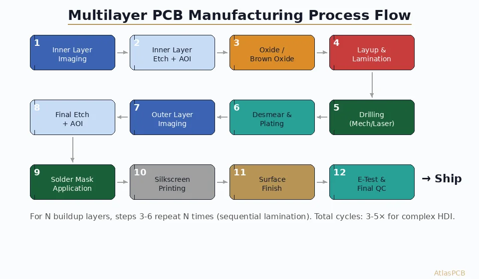
Of the 40 to 60 individual process steps required to manufacture a multilayer printed circuit board, lamination represents the single point where all inner layers become permanently bonded into a unified structure. A defect introduced during etching can be caught by AOI and the layer re-worked. A drilling error affects individual holes that can be plugged and re-drilled. But a lamination failure creates internal defects trapped between bonded layers with no possibility of repair. Delamination, voids, resin starvation, and copper foil wrinkling discovered after lamination result in complete panel scrapping, with all upstream processing time and material cost lost. In our experience manufacturing over 3000 multilayer panels per week, lamination-related defects account for approximately 15 percent of all scrap costs despite representing only one process step.
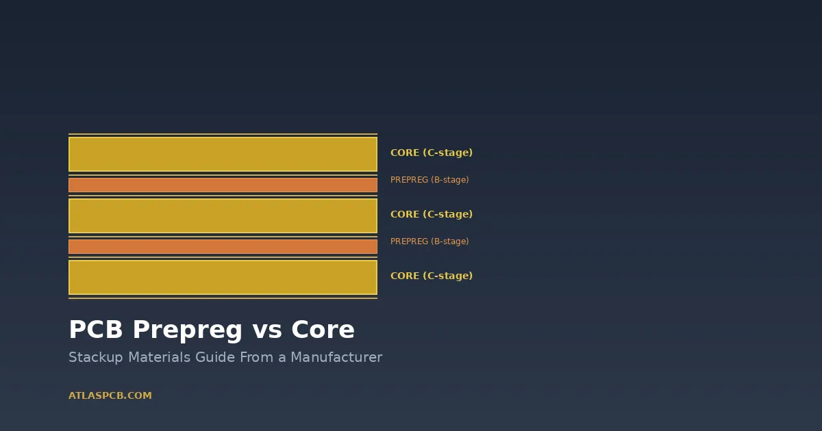
The lamination press transforms a carefully aligned stack of copper-clad cores, prepreg sheets, and copper foils into a solid laminate through the application of heat and pressure over a controlled time cycle. The thermoset resin in the prepreg (pre-impregnated glass fabric) must flow to fill all surface topography, encapsulate inner layer circuits completely, and then crosslink into a rigid matrix without trapping air, moisture, or volatile byproducts. This transformation requires precise control of temperature ramp rate, peak temperature, dwell time, applied pressure, and vacuum level, with optimal parameters varying by resin system, layer count, copper distribution, and panel thickness.
Understanding Prepreg Resin Flow and Gel Point Chemistry
Prepreg behavior during lamination follows a predictable rheological curve that governs the entire process window. At room temperature, the B-staged resin is dry and tack-free. As temperature increases during the lamination ramp, resin viscosity decreases dramatically, dropping from approximately 10,000 poise at 80 degrees Celsius to a minimum of 100 to 500 poise at the minimum viscosity temperature (typically 120 to 140 degrees Celsius for standard FR-4 systems). This low-viscosity window, lasting 10 to 25 minutes depending on the prepreg system, is when resin flows to fill copper topography and air is displaced from the stack.
The gel point occurs when crosslinking reactions progress sufficiently to transform the resin from a viscous liquid to an elastic solid. For standard dicyandiamide-cured FR-4 prepreg, gel point typically occurs at 155 to 165 degrees Celsius after 8 to 12 minutes at temperature. Once gel point is reached, resin flow essentially ceases, and any voids, dry spots, or unfilled regions become permanent defects. Isola’s 370HR prepreg (IPC-4101/126 slash sheet) specifies a gel time of 180 to 240 seconds at 171 degrees Celsius per IPC-TM-650 method 2.3.18, which translates to approximately 15 minutes of flow time during a standard lamination ramp. Understanding this flow-time budget is essential for designing lamination cycles that achieve complete fill without excessive squeeze-out.
Temperature Profile Design: Ramp Rates and Their Effects
The temperature ramp rate during lamination directly affects resin flow behavior and void formation. Rapid ramp rates above 4 degrees Celsius per minute push the stack through the flow window quickly, reducing total flow time and potentially leaving unfilled regions around thick copper features (2-ounce or heavier) on inner layers. Slow ramp rates below 1.5 degrees per minute extend the flow window but allow more time for edge-seal leakage and excessive resin loss from panel margins, potentially causing resin starvation in the panel interior.
Our standard lamination profile for 8 to 12 layer FR-4 boards with 1-ounce copper uses a three-stage temperature program. Stage 1 ramps from ambient to 100 degrees Celsius at 2.5 degrees per minute, allowing moisture absorbed by prepreg and cores to escape without causing explosive vaporization. Stage 2 ramps from 100 to 140 degrees Celsius at 1.8 degrees per minute, providing the extended low-viscosity window needed for complete resin fill. Stage 3 ramps from 140 to 180 degrees Celsius at 3.0 degrees per minute, driving the crosslinking reaction to completion. The total heat-up from room temperature to peak cure temperature requires approximately 55 to 65 minutes, followed by a 60-minute dwell at 180 degrees Celsius to achieve greater than 95 percent cure per DSC (differential scanning calorimetry) analysis. We use Datapaq profiling systems with 12-thermocouple arrays positioned throughout test panels to verify that all regions of the press opening achieve temperature uniformity within plus or minus 3 degrees Celsius of setpoint.
Pressure Application Timing and Multi-Stage Loading
Pressure timing relative to the temperature profile critically affects lamination quality. Applying full pressure too early (before resin reaches minimum viscosity) traps air bubbles that the rigid resin cannot displace. Applying pressure too late (after gel point) means resin has already solidified without conforming to surface topography. The optimal pressure application sequence uses a two-stage or three-stage approach that matches the resin’s rheological state at each temperature.
The first pressure stage applies 50 to 100 psi contact pressure from the start of the cycle through the initial ramp, holding the stack in alignment without compressing air pockets into the resin. At our facility, this initial “kiss pressure” engages when the platen temperature reaches 80 degrees Celsius, ensuring the stack is stable before resin begins flowing. The second pressure stage increases to 250 to 350 psi when the resin reaches its minimum viscosity point (typically detected by the thermocouple in the stack center reaching 130 to 135 degrees Celsius). This full pressure drives resin flow into all surface features and forces trapped air toward the panel edges where it can escape through the stack perimeter. Some high-layer-count constructions (above 16 layers) benefit from a third intermediate pressure stage of 150 to 200 psi applied during the 110 to 125 degree range, providing gentle compression as resin begins softening without trapping air in the still-viscous material.
Vacuum Lamination: Eliminating Air Entrapment in Complex Stackups
Standard hydraulic lamination presses operate at atmospheric pressure within the chamber, relying solely on mechanical pressure to displace air from the stack. For simple 4 to 8 layer boards with uniform copper distribution, this approach works adequately. However, complex HDI stackups with embedded components, thick inner layer copper (3 to 5 ounce), deep circuit relief patterns, or mixed material systems (such as Rogers RF layers bonded to FR-4) benefit enormously from vacuum-assisted lamination that removes air from the stack before resin flow begins.
Vacuum lamination systems from manufacturers including Burkle, Lauffer, and Cedal evacuate the press chamber to below 10 millibar (approximately 7.5 Torr) before heating begins. This 99 percent reduction in ambient pressure removes virtually all trapped air from between prepreg layers, between glass fiber bundles within the prepreg, and from micro-channels along inner layer circuit edges. The absence of air means that resin flow needs only to fill physical topography rather than simultaneously displacing gas bubbles, resulting in dramatically improved fill quality. Our vacuum press (Burkle VLP-95 with 3 openings) achieves vacuum levels of 3 to 5 millibar within 8 minutes of door closure, with total cycle times only 10 to 15 minutes longer than atmospheric lamination due to the pump-down and vent sequences. For boards with layer counts above 12 or copper weights exceeding 2 ounces on inner layers, we default to vacuum lamination regardless of customer specification because the void reduction justifies the marginal cycle time increase.
Copper Distribution and Its Impact on Resin Fill Requirements
Uneven copper distribution across inner layers creates varying resin fill demands that can cause localized resin starvation. A layer with 85 percent copper coverage (typical for ground planes) presents minimal surface topography, requiring only 10 to 15 micrometers of resin fill above the highest copper feature. In contrast, a signal layer with 30 percent copper coverage and isolated 5-mil traces creates 35-micrometer-deep channels between conductors that must be completely filled with resin. When these two extremes exist on adjacent layers separated by a single prepreg sheet, the prepreg must provide radically different resin volumes to different areas of the same panel.
Prepreg selection for copper balancing requires calculating the minimum resin fill volume needed for each interlayer space. The governing equation considers copper thickness (typically 18 to 70 micrometers for 0.5 to 2-ounce foil), copper coverage percentage per layer, and the resulting fill volume requirement in cubic centimeters per square meter. A standard 7628 prepreg (0.19mm pressed thickness, 44 percent resin content) provides approximately 65 micrometers of available fill volume per square meter. This capacity suffices for interlayer gaps between two layers with greater than 60 percent copper coverage each. For interlayer gaps where one or both layers have less than 40 percent copper coverage, specifying 2116 or 1080 prepreg with higher resin content (55 to 65 percent) ensures adequate fill volume. We run fill-volume calculations for every multilayer stackup before assigning prepreg types, using our proprietary calculator that accounts for the as-etched circuit topography extracted from Gerber data.
Managing Resin Squeeze-Out and Edge Seal Integrity
During lamination, pressurized resin flows laterally toward panel edges as well as vertically into circuit topography. Excessive edge squeeze-out reduces resin availability in the panel interior and can cause resin starvation in edge-region circuits located within 15 to 20mm of the panel border. Controlling squeeze-out requires balancing applied pressure (which drives resin movement) against the viscosity window (which determines flow resistance) and the effectiveness of the edge dam or seal that contains lateral flow.
Lamination tooling plates with aluminum or steel caul plates, release films, and precisely dimensioned dam bars control the lamination environment. Dam bars (typically 2 to 3mm thick aluminum strips) placed around the panel perimeter contain lateral resin flow, maintaining internal pressure that forces resin into circuit features rather than allowing it to escape edgewise. The dam bar gap (distance between dam bar and panel edge) should be 2 to 4mm for standard FR-4 and 3 to 5mm for high-flow prepreg systems. Too tight a gap creates excessive back-pressure that can cause resin pooling at panel edges, while too loose a gap allows resin escape and interior starvation. Our lamination fixtures use precision-machined aluminum dam bars with 3mm setback from the panel edge, providing consistent results across all standard panel formats (18x24 inch and 21x24 inch). We verify squeeze-out by measuring pressed panel thickness at 9 points per panel using a micrometer, with acceptable thickness variation of plus or minus 0.05mm (2 mils) from the target.
High Layer Count Challenges: 20+ Layer Boards and Sequential Lamination
Boards with 20 or more layers present unique lamination challenges related to stack height, thermal mass, and cumulative registration error. A 24-layer board at 3.0mm total thickness contains approximately 4.5mm of unbonded material in the stack (due to prepreg thickness exceeding pressed thickness), requiring the press to compress 30 percent of the total stack volume into resin flow without creating voids or wrinkles. The thermal mass of such stacks creates temperature gradients of 15 to 25 degrees Celsius between the outer layers (nearest the heated platens) and the stack center during the ramp phase, meaning that outer prepreg layers reach gel point while center prepreg is still in the flow state.
Sequential lamination addresses these challenges by bonding the complete multilayer in two or more press cycles. A 24-layer sequential construction might bond layers 6 through 19 (a 14-layer sub-stack) in the first lamination cycle, drill and plate blind vias, then add layers 1 through 5 and 20 through 24 in a second lamination cycle. This approach limits each lamination to manageable stack heights where temperature uniformity is achievable, and allows intermediate layer registration verification before committing to the complete structure. However, sequential lamination doubles press time, requires additional alignment fixturing, and subjects inner layers to a second thermal cycle that can advance their cure state beyond optimal. IPC-4101 requires that re-laminated prepreg show less than 2 percent residual volatile content by weight after the initial cycle to remain chemically active for the second bonding step. At our facility, we process sequential laminations for boards above 16 layers as standard practice, with single-press lamination reserved for constructions of 14 layers or fewer where uniform cure is achievable.
Cure Verification: DSC Analysis and Tg Confirmation
Confirming complete cure after lamination ensures long-term reliability and prevents field failures from under-cured resin systems. Differential scanning calorimetry (DSC) per IPC-TM-650 method 2.4.25 measures the residual cure exotherm remaining in a laminate sample. A fully cured laminate shows no exothermic peak during the DSC scan, while an under-cured sample exhibits a residual peak proportional to the remaining reactive groups. The industry standard requires greater than 95 percent cure for Class 3 applications, calculated as the ratio of the residual exotherm to the total available cure energy measured on uncured prepreg.
Glass transition temperature (Tg) measurement via DSC or TMA (thermomechanical analysis) provides a complementary cure verification method. Under-cured laminates exhibit depressed Tg values, typically 5 to 15 degrees below the fully-cured specification. For Isola 370HR (specified Tg of 180 degrees Celsius by DSC), a measured Tg below 170 degrees indicates insufficient cure requiring investigation. Common causes include thermocouple failure masking actual temperature below setpoint, premature press opening before full dwell completion, or out-of-specification prepreg with degraded catalyst activity. Our quality lab performs DSC analysis on 2 samples per production lot for standard production and 4 samples per lot for aerospace and automotive programs, with test results archived for 10 years per our AS9100 quality system requirements. Total cure verification adds approximately 4 hours to the production cycle (including sample preparation and instrument time) but catches under-cure conditions before panels proceed to drilling and plating operations where the defect would be invisible.
Post-Lamination Inspection: Ultrasonic Scanning and Visual Methods
Non-destructive inspection after lamination detects internal voids, delamination, and resin starvation before committing panels to subsequent processing steps. C-mode scanning acoustic microscopy (C-SAM) uses high-frequency ultrasound (typically 25 to 50 MHz transducers) to map internal interfaces, detecting air gaps as small as 50 micrometers in diameter. The technique scans the panel in a water-immersion tank with resolution of 0.2mm lateral and 0.05mm depth positioning, producing color-coded maps showing the bonding quality at each interface.
For production monitoring, we perform C-SAM inspection on the first 3 panels of each new layup configuration and on statistical samples (1 in 20 panels) during continuous production runs. Acceptance criteria follow IPC-6012 section 3.6.2, requiring no delamination or voids larger than 1 percent of the board area. For aerospace Class 3/A production, the criteria tighten to zero allowable voids at any interface. Visual inspection under 10x magnification catches edge delamination, resin bleed patterns, and surface anomalies that indicate internal problems. An experienced inspector can identify panels with lamination issues from edge appearance alone, as under-cured panels show a distinctly lighter resin color at the edges compared to properly cured material. Our inspection team evaluates 100 percent of panel edges after trimming, quarantining any panel showing suspicious coloration or texture for C-SAM verification before release to drilling.
Process Control: SPC Monitoring of Key Lamination Parameters
Statistical process control (SPC) applied to lamination parameters provides early warning of drift before defects reach the product. The key monitored parameters include peak temperature at 4 locations per opening (target plus or minus 2 degrees Celsius), pressure at maximum load (target plus or minus 15 psi), vacuum level at start of heating (target below 10 millibar), total cycle time (target plus or minus 5 minutes), and pressed panel thickness at 9 locations (target plus or minus 0.05mm). Each parameter feeds into control charts with action limits set at 2-sigma and control limits at 3-sigma from the process mean.
Our lamination presses log all parameters digitally at 30-second intervals throughout each cycle, storing complete cycle records for 5 years per customer traceability requirements. The monitoring system generates automatic alerts when any parameter exceeds action limits, triggering real-time review by the process engineer before the cycle completes. This proactive approach caught 14 potential issues in Q2 2026 alone, including a heating element degradation that was creating a 5-degree cold spot in opening 2 of our main press, a vacuum pump leak reducing ultimate vacuum to 18 millibar, and a pressure transducer calibration drift of 22 psi. Each of these issues would have produced defective product within 1 to 3 production shifts if not detected through SPC monitoring, validating the investment in comprehensive process data collection. The total lamination reject rate across our facility averages 0.8 percent of panels pressed, with our target of 0.5 percent driving continuous improvement initiatives on press maintenance scheduling and prepreg storage control.
Reviewed by AtlasPCB Engineering Team
Complex Multilayer Stackup? Get Expert Manufacturing Support
Our process engineers optimize lamination parameters for your specific layer count and material combination. Submit your stackup for a free manufacturability review.
Get Your Quote →About AtlasPCB — We specialize in complex PCB manufacturing for HDI, RF, and high-reliability applications. Explore our multilayer PCB fabrication up to 30 layers, or get an full PCB manufacturing capabilities . Every order includes free engineering review. Get your quote.
Reviewed by AtlasPCB Engineering Team — IPC-certified manufacturing specialists with 15+ years of production experience in HDI, RF, and high-reliability PCB fabrication. Content based on factory floor data and real customer design reviews.
- PCB lamination
- multilayer bonding
- prepreg cure
- vacuum lamination
- IPC-4101
- process control