· AtlasPCB Engineering Team · Engineering · 14 min read
Copper Electroplating Chemistry for Void-Free Microvia Filling: Acid Bath Additives and Process Control
Understanding the critical role of levelers, brighteners, and suppressors in acid copper plating baths enables manufacturers to achieve void-free microvia fills that meet IPC-6012 Class 3 reliability standards.
Why Microvia Fill Quality Determines HDI Board Reliability
The transition from simple through-hole plating to filled microvia technology represents one of the most demanding process challenges in modern PCB manufacturing. When a blind via measuring 100 micrometers in diameter and 65 micrometers deep must be filled completely with copper, the electroplating chemistry determines whether that via will survive 1000 thermal cycles or fail within 200. IPC-6012 Class 3 mandates less than 25 percent void content in filled microvias, while many OEMs now specify zero visible voids under cross-section analysis at 200x magnification. At our facility, we process over 4000 panels per month with filled microvias, and the plating bath chemistry is the single most critical variable we monitor.
The acid copper sulfate bath used for via filling is fundamentally different from the conformal plating bath used for through-hole coverage. While conformal plating targets uniform 25 micrometer deposits across all surfaces, via filling requires preferential deposition at the bottom of the cavity while suppressing growth at the opening. This selective deposition behavior is entirely controlled by organic additives that interact with the copper surface at the molecular level. Without proper additive management, the via opening closes before the bottom fills, trapping electrolyte and creating the infamous “keyhole” void that compromises long-term reliability.
The Three-Component Additive System in Acid Copper Baths
Modern via-filling plating baths rely on a three-component organic additive system: suppressors (also called carriers), brighteners (also called accelerators), and levelers. Each additive performs a distinct electrochemical function, and their concentrations must be maintained within tight ranges, typically plus or minus 10 percent of target values. The base electrolyte consists of copper sulfate pentahydrate at 200 to 250 grams per liter, sulfuric acid at 50 to 80 grams per liter, and chloride ions at 40 to 70 parts per million. This foundation chemistry provides the copper ions for deposition, but without the organic additives, the deposit would be rough, porous, and completely unsuitable for microvia filling.
Suppressor molecules are high molecular weight polyethylene glycol (PEG) compounds with molecular weights ranging from 2000 to 8000 daltons. These molecules adsorb strongly on copper surfaces in the presence of chloride ions, forming a blocking layer that reduces the local plating rate by 30 to 50 percent. The suppressor preferentially accumulates on exposed, convex surfaces near the via opening because these regions receive more fresh electrolyte through convection. This differential adsorption creates the initial condition for bottom-up filling by slowing deposition where it is least needed.
How Brighteners Drive Bottom-Up Filling
Brighteners, technically known as accelerators, are small sulfur-containing organic molecules such as bis(3-sulfopropyl) disulfide (SPS) or 3-mercapto-1-propanesulfonate (MPS). With molecular weights below 500 daltons, these compact molecules can diffuse into recessed features far more readily than the larger suppressor molecules. Once adsorbed on the copper surface at the via bottom, brighteners displace the suppressor layer and locally increase the plating rate by 40 to 80 percent. This mechanism creates the “super-filling” effect where copper deposition at the via bottom outpaces deposition at the opening.
The concentration of brightener in a typical via-fill bath ranges from 2 to 12 milliliters per liter, depending on the proprietary formulation. What makes brightener chemistry particularly interesting is the concept of area concentration. As copper fills the via from the bottom upward, the surface area at the bottom decreases while brightener molecules remain adsorbed. This concentrating effect progressively increases the local accelerator coverage and plating rate, creating a positive feedback loop that drives increasingly rapid bottom-up growth. In our production baths, we maintain brightener at 6.5 milliliters per liter with daily CVS (cyclic voltammetric stripping) analysis to ensure consistent fill performance across panel production runs of 200 to 300 panels between bath adjustments.
The Role of Levelers in Preventing Overfill and Dimpling
Levelers are the most chemically complex component in the additive system, typically consisting of nitrogen-containing heterocyclic compounds such as Janus Green B derivatives or proprietary polyamine structures. These molecules selectively adsorb on high-current-density regions, specifically the protruding copper growth front as the via approaches complete fill. By suppressing deposition on these raised areas, levelers prevent the formation of bumps or mounds above filled vias, which would create problems during subsequent lamination or surface planarization steps.
Leveler concentration is maintained at 1 to 5 milliliters per liter in most commercial via-fill formulations. Unlike suppressors, levelers are consumed during the plating process through reduction at the cathode surface, meaning their effective concentration decreases with plating time and must be replenished based on ampere-hour consumption. At a typical current density of 1.5 to 2.5 amperes per square decimeter used for via filling, leveler consumption runs approximately 0.3 milliliters per 1000 ampere-hours. We track leveler depletion using a combination of CVS analysis and Hull cell testing every 4 hours during continuous production, adjusting additions based on total throughput rather than fixed time intervals.
Chloride Ion Management and Its Impact on Additive Performance
Chloride ions serve as a critical co-factor for suppressor adsorption, yet their concentration window is remarkably narrow. Below 40 parts per million, suppressor molecules cannot form effective blocking layers, and the bath loses its filling capability. Above 80 parts per million, excessive chloride promotes rough, nodular deposits and can interfere with brightener activity. This 40-ppm operating window requires careful monitoring, especially in high-throughput production where drag-in from rinse tanks and breakdown of chloride-containing organic additives can shift levels within a single production shift.
The interaction between chloride and copper chloride bridge formation creates the physical anchoring mechanism for PEG-type suppressors. Each suppressor molecule requires approximately 3 to 5 chloride ions to form a stable adsorption complex on the copper surface. When chloride drops below the critical threshold, suppressor effectiveness diminishes exponentially rather than linearly, making the process window extremely sensitive to chloride depletion. Our laboratory performs chloride analysis via silver nitrate titration twice per shift, with automated dosing systems maintaining levels at 55 plus or minus 8 parts per million. Rohm and Haas (now part of DuPont Electronics) first characterized this chloride-suppressor interaction in their Copper Gleam formulations, and the fundamental chemistry remains central to all modern via-fill systems.
Current Density and Waveform Optimization for Filled Microvias
The plating current density and waveform profoundly influence fill quality. Direct current (DC) plating at constant current density provides the simplest approach but offers limited control over deposit morphology. Most advanced via-fill processes employ pulse-reverse plating, where short cathodic pulses (5 to 20 milliseconds) alternate with brief anodic pulses (1 to 3 milliseconds) and off-times. The cathodic pulse drives copper deposition, while the anodic pulse selectively dissolves copper from high-current-density areas at the via opening, effectively enhancing the bottom-up filling ratio.
A typical pulse-reverse waveform for 100-micrometer blind via filling uses a cathodic current density of 2.0 A/dm2 for 15 milliseconds, followed by a reverse pulse at 0.8 A/dm2 for 2 milliseconds, with a 3-millisecond off-time between cycles. This ratio produces an effective average current density of approximately 1.4 A/dm2, requiring 55 to 65 minutes to achieve complete fill of a 65-micrometer-deep via. The pulse parameters must be optimized for the specific via geometry, as deeper vias with aspect ratios above 0.8 to 1 generally require longer off-times to allow diffusion refreshment of depleted electrolyte at the via bottom. MacDermid Alpha’s iGalvo system and Atotech’s Inpulse2 both provide programmable pulse-reverse rectifiers designed specifically for via-fill applications, with recipe storage for multiple via geometries.
Process Monitoring: CVS Analysis and Hull Cell Testing
Cyclic voltammetric stripping (CVS) analysis remains the primary analytical method for monitoring organic additive concentrations in acid copper baths. The technique measures the mass of copper deposited and stripped from a rotating disk electrode under controlled potential cycling, with the stripping charge proportional to additive activity. Commercial CVS analyzers from companies like ECI Technology (Qualilab system) and PhoenixPLC provide automated sampling and measurement with results available in under 15 minutes per analysis.
CVS testing produces three key values: suppressor activity (Sa), brightener activity (Ba), and leveler activity (La), each reported as a percentage relative to a reference bath standard. Acceptable ranges for via-fill applications typically require Sa between 90 and 110 percent, Ba between 85 and 115 percent, and La between 80 and 120 percent of standard values. When any parameter drifts outside these limits, targeted additions bring the bath back into specification. In our production environment, we perform CVS analysis 4 times during each 24-hour production cycle, with immediate corrective dosing triggered when any value exceeds plus or minus 8 percent of target. This frequency catches drift before it manifests as fill defects, which would only become visible during cross-section analysis hours after plating completion.
Temperature and Agitation Control for Uniform Via Fill
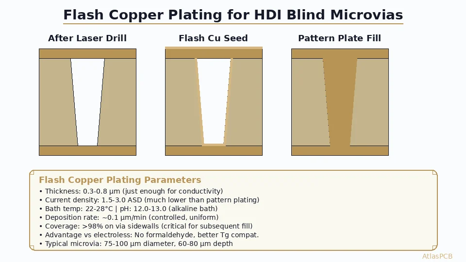
Bath temperature directly affects plating rate, additive activity, and mass transport within microvias. Most via-fill baths operate between 22 and 28 degrees Celsius, with 25 degrees Celsius being the most common target temperature. A 2-degree increase above the optimal point can accelerate brightener consumption by 15 to 20 percent, shifting the suppressor-to-brightener balance and potentially causing under-filled vias. Conversely, temperatures below 22 degrees Celsius reduce ion mobility sufficiently to create concentration gradients within deep vias, leading to center voids.
Agitation serves the dual purpose of refreshing depleted electrolyte at the cathode surface and distributing heat uniformly throughout the bath. Panel agitation rates of 1 to 3 meters per minute using eductor-based or air-bubble systems provide adequate solution movement for most via geometries. However, excessive agitation can strip weakly adsorbed brightener molecules from the via bottom, defeating the area-concentration mechanism essential for super-filling. The balance point varies by via diameter: smaller 75-micrometer vias require gentler agitation than larger 150-micrometer vias because the diffusion path into smaller features is more easily disrupted by bulk solution movement. Atotech’s research published at IPC APEX 2025 demonstrated that oscillating panel movement at 2 meters per minute with 1-second reversals provided optimal fill for via diameters from 80 to 120 micrometers across a 500x600mm panel format.
Common Fill Defects and Their Root Causes
Understanding the relationship between plating chemistry and fill defects allows rapid troubleshooting when issues arise. The four most common defects in microvia filling are keyhole voids (center voids), seam voids (vertical line defects), dimples (incomplete surface closure), and bumps (overfill). Each defect has a distinct chemical origin. Keyhole voids indicate insufficient brightener activity or excessive suppressor, causing premature closure of the via opening before the bottom fills. Seam voids result from inadequate agitation that prevents electrolyte refreshment at the via center, creating a copper-depleted zone that remains unfilled.
Dimples occur when leveler activity is too high relative to brightener, suppressing the final growth that would close the via surface flush with the surrounding copper. Bumps indicate the opposite condition: insufficient leveler allowing uncontrolled growth above the filled via. In production, we track defect rates through statistical process control (SPC) charts, sampling 5 microsections per production lot. Our target defect rate is below 0.3 percent for Class 3 production, with immediate lot hold and bath analysis triggered when any sample shows voids exceeding 10 percent of the via cross-sectional area. IPC-TM-650 method 2.1.1 defines the microsectioning procedure, while IPC-6012 revision ES (2024) establishes the acceptance criteria for filled microvia quality.
Anode Management and Copper Ion Replenishment
The anode system in a via-fill plating bath requires careful management to maintain consistent copper ion concentration and prevent particulate contamination. Phosphorized copper anodes containing 0.04 to 0.06 percent phosphorus produce a black oxide film during dissolution that prevents excessive copper ion release and reduces particulate generation. The phosphorus content must be verified for each anode lot, as values below 0.03 percent result in rough anode surfaces that shed copper particles into the bath, creating nodule defects on plated surfaces.
Anode-to-cathode area ratio should be maintained between 1:1 and 2:1 for optimal current distribution. Titanium anode baskets with polypropylene bags provide filtration of anode sludge, with bag replacement every 500 to 800 production hours depending on current loading. Copper ion concentration in the bath drifts naturally due to imbalances between anodic dissolution and cathodic deposition efficiency (which runs approximately 95 to 98 percent in acid copper baths). Copper sulfate analysis via titration or UV-Vis spectroscopy every 12 hours ensures concentration remains within the 200 to 250 grams per liter target range. When copper concentration drops below 190 grams per liter, we add pre-dissolved copper sulfate concentrate; above 260 grams per liter, we reduce anode area by removing baskets from the circuit.
Interaction Between Via Geometry and Chemistry Requirements
Via aspect ratio (depth divided by diameter) dramatically influences the chemistry requirements for successful filling. Low aspect ratio vias (0.5:1, such as 50 micrometers deep by 100 micrometers diameter) fill readily with standard additive concentrations and moderate agitation. As aspect ratio increases toward 1:1 (such as 100 micrometers deep by 100 micrometers diameter), the diffusion limitations become severe, requiring higher brightener concentrations, optimized pulse-reverse waveforms, and precisely controlled agitation to avoid center voids.
For aspect ratios exceeding 1:1, some manufacturers employ a two-step filling approach: an initial conformal plating phase at low current density (0.5 A/dm2) to establish a seed layer deep in the via, followed by the filling phase at higher current density with full additive activity. This approach reduces the effective aspect ratio during the critical filling phase, improving success rates for challenging geometries. IPC-2226 Level C HDI structures requiring stacked filled microvias at 1.2:1 aspect ratio represent the upper boundary of what standard single-step filling chemistry can achieve. Beyond this point, manufacturers typically transition to copper paste filling or conductive epoxy alternatives, accepting the trade-off of lower thermal and electrical conductivity. In our experience processing HDI boards for smartphone and wearable applications, the 0.8:1 to 1.0:1 aspect ratio range is where chemistry optimization delivers the highest return on investment, representing approximately 65 percent of our filled via production volume.
Bath Life Management and Carbon Treatment
Acid copper via-fill baths have finite operating lives, typically measured in thousands of ampere-hours or months of continuous operation. Organic additive breakdown products accumulate over time, increasing bath viscosity and interfering with fresh additive performance. The primary breakdown pathway involves oxidation of suppressor molecules at the anode, producing lower molecular weight fragments that no longer provide effective surface blocking. These fragments compete with functional additive molecules for adsorption sites without delivering the desired electrochemical effect.
Carbon treatment using activated carbon powder at 2 to 5 grams per liter removes accumulated organic breakdown products, effectively resetting the bath to near-new condition. We perform carbon treatment every 4000 to 6000 ampere-hours, or when CVS analysis shows increasing divergence between calculated and actual additive concentrations. The procedure involves adding activated carbon, circulating for 2 to 4 hours with air agitation, then filtering through 1-micrometer cartridge filters to remove all carbon particles. Following carbon treatment, all three additives must be replenished to target concentrations, and a qualification panel with test coupons must pass cross-section analysis before production resumes. Dow Chemical’s Microfab via-fill chemistry documentation recommends carbon treatment when the cumulative organic breakdown index exceeds 150 percent of initial bath values, a metric derived from the difference between CVS-measured and titration-measured additive concentrations.
Quality Verification and Cross-Section Standards
The ultimate verification of via-fill quality comes from destructive cross-section analysis per IPC-TM-650 Method 2.1.1. Technicians mount test coupons in epoxy, grind to the via center, polish to 0.05-micrometer alumina finish, and examine under optical microscopy at 100x to 500x magnification. The cross-section reveals fill completeness, void percentage, dimple depth, surface planarity, and copper grain structure. For IPC-6012 Class 3 compliance, the fill must be at least 75 percent of the via depth, with no single void exceeding 25 percent of the via cross-sectional area.
Many automotive and aerospace OEMs impose stricter requirements through their own procurement specifications. Tesla’s procurement specification for battery management system PCBs requires greater than 95 percent fill with less than 5 percent total void area, verified on every production panel using dedicated test coupons. We process 12 to 15 cross-sections daily as part of our statistical process control program, with results feeding directly into our bath maintenance decision matrix. Any cross-section showing fill below 80 percent triggers immediate lot quarantine and emergency CVS analysis, followed by corrective chemistry adjustments before the next panel enters the plating line. This closed-loop quality system has maintained our first-pass fill yield above 99.2 percent across the past 18 months of production.
Reviewed by AtlasPCB Engineering Team
Need Void-Free Microvia Filling for Your HDI Design?
Our plating engineers optimize chemistry and process parameters for your specific via geometry. Get a DFM review and quote within 24 hours.
Get Your Quote →About AtlasPCB — We specialize in complex PCB manufacturing for HDI, RF, and high-reliability applications. Explore our HDI PCB manufacturing capabilities, full PCB manufacturing capabilities, or get an impedance-controlled PCB manufacturing . Every order includes free engineering review. Get your quote.
Reviewed by AtlasPCB Engineering Team — IPC-certified manufacturing specialists with 15+ years of production experience in HDI, RF, and high-reliability PCB fabrication. Content based on factory floor data and real customer design reviews.
- copper plating
- microvia filling
- HDI manufacturing
- electroplating chemistry
- acid copper bath
- IPC-6012