· AtlasPCB Engineering · Engineering · 16 min read
PCB Fiber Weave Effect on Signal Skew: Causes, Impact & Mitigation for High-Speed Design
Understand how glass fiber weave patterns cause signal skew in high-speed PCBs. Learn mitigation techniques including trace rotation, spread glass, and material selection.

Understanding the Fiber Weave Effect in PCB Substrates
Every high-speed PCB designer eventually encounters a problem that cannot be solved by tighter impedance tolerances or better stackup calculations alone. Differential pairs that look perfect in simulation fail during compliance testing. Eye diagrams close unexpectedly. Bit error rates climb despite textbook routing. The culprit is often invisible in standard 2D design tools — it is the fiber weave effect, a fundamental consequence of how PCB laminates are constructed.
The fiber weave effect arises because the glass-reinforced substrates used in virtually all PCB laminates are not homogeneous materials. The woven glass fabric that provides mechanical strength creates a periodic pattern of glass-rich bundles and resin-filled gaps, each with dramatically different dielectric constants. When high-speed signals traverse these alternating regions, they experience varying propagation velocities that translate directly into [signal integrity]/blog/signal-integrity-pcb-design-guide/) degradation — most critically, intra-pair skew in differential signaling.
For designs operating at 10 Gbps and below, the fiber weave effect was a secondary concern. At 25 Gbps, 56 Gbps PAM4, and especially 112G SerDes data rates, it has become a primary design constraint that demands attention from the earliest stages of [material selection]/blog/pcb-material-selection-guide/) and stackup planning.
The Physics: Glass Fiber Weave Structure and Dk Variation
How PCB Laminates Are Constructed
PCB substrates consist of woven E-glass (or specialty glass) fabric impregnated with resin — typically epoxy, PPO, or PTFE-based systems. The glass fabric is woven from yarn bundles in a plain-weave or twill pattern, creating an interlocking grid of warp (machine direction) and fill (cross direction) threads.
Each yarn bundle contains hundreds of individual glass filaments, typically 5–9 μm in diameter. These bundles are woven on looms with specific thread counts and bundle thicknesses defined by glass style numbers standardized by IPC (e.g., 1080, 2116, 1078, 3313).
The critical point: after weaving, the fabric has a periodic structure with:
- Knuckle regions — where warp and fill bundles overlap, creating the thickest glass concentration
- Bundle regions — where individual warp or fill bundles run between crossover points
- Window regions — open areas between bundles filled entirely with resin
The Dielectric Constant Mismatch
The fiber weave effect exists because glass and resin have fundamentally different dielectric properties:
| Material | Dk (at 10 GHz) | Loss Tangent (Df) |
|---|---|---|
| E-glass fiber | ~6.2 | ~0.004 |
| Standard epoxy resin | ~3.0–3.5 | ~0.010–0.020 |
| Low-Dk resin (PPO blend) | ~2.8–3.2 | ~0.003–0.008 |
| NE-glass fiber | ~4.4 | ~0.002 |
The composite Dk of a finished laminate — the value quoted on datasheets — is an average of these constituent materials weighted by their volume fractions. A typical FR-4 laminate might have a published Dk of 4.2 at 1 GHz, but this average conceals localized Dk variations from roughly 3.2 to 5.5 depending on whether a signal encounters a resin pocket or a glass bundle.
For a deeper analysis of how Dk values affect [high-speed material performance]/blog/pcb-high-speed-material-dk-df-comparison/), understanding this micro-scale variation is essential.
Signal Propagation Velocity Depends on Local Dk
The propagation velocity of an electromagnetic wave in a transmission line is:
v = c / √(Dk_eff)
where c is the speed of light and Dk_eff is the effective dielectric constant experienced by the signal. A signal propagating over a glass-rich region (Dk_eff ≈ 5.0–5.5) travels significantly slower than one propagating over a resin-rich region (Dk_eff ≈ 3.2–3.5).
The velocity difference can be calculated:
- Over glass: v_glass = c / √5.5 ≈ 0.426c ≈ 5.03 in/ns
- Over resin: v_resin = c / √3.2 ≈ 0.559c ≈ 6.60 in/ns
This represents a ~31% velocity difference between the two extremes. While real traces average over multiple weave periods, even partial exposure to this variation creates measurable skew.
How Skew Develops in Differential Pairs
The Mechanism of Intra-Pair Skew
[Differential pair routing]/blog/differential-pair-routing-pcb/) relies on the assumption that both traces of a pair experience identical propagation conditions. When both traces see the same effective Dk, they arrive at the receiver in phase — the differential signal is clean.
The fiber weave effect breaks this assumption. Consider a differential pair with 5-mil traces on 10-mil center-to-center spacing, routed parallel to the warp direction of a 1080 glass style. The 1080 weave has a bundle pitch of approximately 47 mils in the warp direction and 37 mils in the fill direction.
In the worst case:
- Trace P (positive) aligns directly over a glass yarn bundle → sees Dk_eff ≈ 4.8–5.2
- Trace N (negative) falls in the resin window between bundles → sees Dk_eff ≈ 3.2–3.8
The velocity difference between P and N creates a propagation delay mismatch that accumulates linearly with trace length. This is intra-pair skew — not caused by routing length mismatch, but by the dielectric environment.
Why Weave Alignment Matters
The severity of the skew depends critically on how the traces align with the weave:
- 0° routing (parallel to warp or fill) — Worst case. A trace can “track” along a single bundle or window for the entire route length, maintaining the same Dk offset continuously.
- 45° routing — Better, but can still align with the diagonal of the weave pattern.
- Arbitrary angles (7°, 11°, 14.5°) — Best. The trace crosses multiple bundles and windows over short distances, effectively averaging the Dk variations.
The weave pitch and trace spacing interact to create specific resonance conditions. When the differential pair spacing is an integer multiple of the half-weave pitch, the two traces can lock onto alternating glass/resin regions — maximizing skew.
Quantifying the Impact: Skew Budgets and Protocol Requirements
Measured Skew Values by Glass Style
Industry measurements and simulation studies consistently show the following skew ranges for differential pairs on standard glass weave styles, routed at 0° to the warp direction:
| Glass Style | Weave Type | Bundle Pitch (mil) | Typical Skew (ps/in) | Window Size |
|---|---|---|---|---|
| 106 | Standard | 45 × 35 | 3–8 | Small |
| 1080 | Standard | 47 × 37 | 5–15 | Medium |
| 2116 | Standard | 50 × 42 | 8–18 | Large |
| 7628 | Standard | 55 × 47 | 10–25 | Very Large |
| 1078 | Spread glass | ~47 (flat) | 1–3 | Minimal |
| 3313 | Spread glass | ~50 (flat) | 1–4 | Minimal |
| 1067 | Spread glass | ~35 (flat) | 0.5–2 | Minimal |
| 2113 | Spread glass | ~42 (flat) | 1–3 | Minimal |
The difference between standard and spread glass styles is dramatic — spread glass reduces skew by 5–10× for the same routing angle.
High-Speed Protocol Timing Budgets
To understand whether fiber weave skew matters for a specific design, compare it to the protocol’s timing budget:
| Protocol | Data Rate | Unit Interval (UI) | Skew Budget (typical) | Max Tolerable Skew |
|---|---|---|---|---|
| PCIe Gen3 | 8 GT/s | 125 ps | ~15 ps | ~30 ps |
| PCIe Gen4 | 16 GT/s | 62.5 ps | ~8 ps | ~15 ps |
| PCIe Gen5 | 32 GT/s | 31.25 ps | ~4 ps | ~8 ps |
| PCIe Gen6 | 64 GT/s (PAM4) | 31.25 ps | ~3 ps | ~6 ps |
| 56G PAM4 | 56 Gbps | 35.7 ps | ~4 ps | ~7 ps |
| 112G PAM4 | 112 Gbps | 17.9 ps | ~2 ps | ~4 ps |
Consider a 6-inch differential pair on standard 2116 glass routed at 0°. With 10 ps/inch of skew, the total intra-pair skew reaches 60 ps — catastrophic for anything above PCIe Gen3. Even at PCIe Gen4, this exceeds the entire skew budget by 4×.
For [high-speed PCB design]/blog/high-speed-pcb-design/) targeting modern protocols, the fiber weave effect is not optional to address — it is a gating requirement.
Glass Weave Styles: Standard vs. Spread Glass
Standard Weave Styles
Standard glass weave styles (106, 1080, 2116, 7628) use round or lightly flattened yarn bundles woven in a plain-weave pattern. The key characteristics:
- Distinct bundle and window regions with sharp boundaries
- Significant Dk variation across the weave period
- Lower cost and broad availability
- Adequate for designs below 10 Gbps with proper routing techniques
The 1080 style is the workhorse of the PCB industry — thin enough for fine-pitch multilayer stackups, widely available, and well-characterized. However, its open weave pattern with relatively large resin windows makes it one of the more problematic styles for fiber weave skew.
The 2116 style offers more glass content and greater mechanical stability but has even larger bundle pitches and window regions, making the Dk variation more pronounced.
Spread Glass (Flat Fiber) Technology
Spread glass technology — also called flat fiber or open-fiber weave — fundamentally changes the glass fabric structure:
- Yarn bundles are mechanically spread (flattened) before weaving, increasing their width by 2–3×
- Flattened bundles overlap at crossover points, eliminating or greatly reducing resin windows
- The resulting fabric has near-uniform glass distribution across its surface
Popular spread glass styles include:
- 1078 — Spread version of 1080, extremely uniform Dk distribution
- 3313 — Medium-weight spread glass, excellent balance of uniformity and mechanical properties
- 1067 — Ultra-thin spread glass for fine-pitch HDI applications
- 2113 — Spread version of 2116, combining higher glass content with uniformity
The Dk variation across spread glass fabric is typically ±0.1 or less, compared to ±0.5 to ±1.0 for standard weaves. This translates directly to the 5–10× skew reduction shown in the table above.
Cost and Availability Considerations
Spread glass fabrics command a 15–30% premium over standard equivalents, and their availability varies by region and supplier. However, this cost increase is often far less than the alternative — redesigning a board, adding equalization complexity, or accepting yield loss from signal integrity failures.
For production volumes, spread glass materials from major laminate suppliers are readily available with lead times comparable to standard materials.
NE-Glass and Low-Dk Glass Technologies
The NE-Glass Approach
An alternative to changing the weave geometry is changing the glass composition itself. NE-glass (also called L-glass or low-Dk glass) replaces the standard E-glass formulation with a modified composition that lowers the glass Dk from ~6.2 to ~4.4:
| Glass Type | Dk (10 GHz) | Df (10 GHz) | CTE (ppm/°C) |
|---|---|---|---|
| E-glass | ~6.2 | ~0.004 | ~5.5 |
| NE-glass | ~4.4 | ~0.002 | ~3.0 |
| S-glass | ~5.2 | ~0.003 | ~2.9 |
| Quartz | ~3.8 | ~0.0001 | ~0.5 |
By reducing the Dk contrast between glass and resin from ~3.0 (E-glass vs. standard resin) to ~1.2 (NE-glass vs. standard resin), the fiber weave effect is reduced by approximately 60% even with standard weave patterns.
Combining Spread Glass with NE-Glass
The ultimate solution for extreme-speed applications is combining spread glass fabric with NE-glass composition. This attacks the problem from both directions:
- Spread glass eliminates geometric Dk variation (no resin windows)
- NE-glass reduces the remaining Dk contrast at bundle boundaries
Together, they reduce fiber-weave-induced skew to under 0.5 ps/inch — effectively eliminating it as a design concern even for 112G SerDes channels.
Materials using this combined approach (NE-glass + spread weave) are available from major laminate suppliers and are increasingly specified for data center switch, AI accelerator, and 800G optical transceiver applications.
Trace Routing Angle Strategies
The Rotation Principle
When spread glass or NE-glass materials are not available or not in the budget, the most effective layout-level mitigation is routing traces at a non-zero angle relative to the glass weave pattern.
The principle is simple: if a trace crosses multiple weave periods over a short distance, the localized Dk variations are averaged out. The trace experiences the composite (datasheet) Dk rather than the extreme glass or resin Dk.
Optimal Routing Angles
The optimal angle depends on the specific glass style and the differential pair geometry, but general guidelines apply:
- 0° and 90° — Avoid entirely for critical signals. These align traces parallel to warp and fill bundles.
- 45° — Better than 0°/90° but can align with the weave diagonal in some styles.
- 7° to 15° — The recommended range. Angles in this range ensure that traces cross multiple warp and fill bundles within a few hundred mils of routing.
- Non-round angles (e.g., 11.3°, 14.04°) — Some designers use specific irrational angles to prevent any periodic alignment with the weave.
Practical Implementation Challenges
Angled routing presents real-world challenges:
- Increased routing area — Angled traces consume more board real estate than Manhattan (0°/90°) routing.
- EDA tool limitations — Not all routing tools handle arbitrary-angle routing efficiently. Many require manual intervention.
- Connector pin-out constraints — Connectors typically have pins on 0°/90° grids, requiring transitions from angled to Manhattan routing at breakout regions.
- Manufacturing considerations — Acute-angle traces can create acid traps during etching, though modern fabrication processes handle angles above 5° without issue.
A practical compromise: route the long, straight sections of differential pairs at 7–15° angles, while using standard 0°/90° routing for short breakout regions near connectors and components. The breakout regions are typically short enough (<1 inch) that accumulated skew is negligible.
Impedance Variation: The Other Fiber Weave Problem
While skew dominates the discussion, the fiber weave effect also causes impedance variation along single-ended and differential traces. As the local Dk changes, so does the characteristic impedance:
Z₀ ∝ 1 / √(Dk_eff)
A trace routed over alternating glass and resin regions experiences periodic impedance bumps. For a nominal 50-ohm trace, the impedance might vary between 46 and 55 ohms as it crosses weave features. Each impedance discontinuity creates a small reflection, and when these reflections are periodic, they can create resonant nulls in the channel insertion loss at specific frequencies.
This effect is distinct from the random impedance variation addressed by standard [impedance control]/blog/pcb-impedance-control/) processes. Standard TDR measurements average over several weave periods and may not capture the micro-scale variation. The resonant effect appears as periodic dips in S21 (insertion loss) that worsen at higher frequencies.
For channels targeting 56 Gbps and above, impedance variation from fiber weave should be accounted for in channel simulation alongside the skew effect. Understanding [dielectric constant measurement]/blog/pcb-dielectric-constant-dk-measurement/) techniques helps engineers distinguish between bulk Dk and localized Dk variations.
Simulation and Measurement Approaches
Electromagnetic Simulation
Accurate simulation of the fiber weave effect requires 3D electromagnetic (EM) solvers that can model the actual weave geometry:
- Create a geometric model of the glass weave pattern, including bundle dimensions, pitch, and window size for the target glass style.
- Assign material properties — glass regions get Dk = 6.2 (E-glass) or 4.4 (NE-glass); resin regions get the specific resin Dk.
- Place differential pair traces at the desired angle and spacing relative to the weave model.
- Run full-wave simulation (FDTD or FEM) to extract S-parameters, propagation delay, and impedance profiles.
This process is computationally expensive but provides accurate predictions of skew, impedance variation, and insertion loss resonances. It is especially valuable when evaluating trade-offs between glass styles, routing angles, and material systems before committing to fabrication.
Physical Measurement Techniques
After fabrication, the fiber weave effect can be measured through:
- Time Domain Reflectometry (TDR) — High-bandwidth TDR (≥20 GHz) can reveal periodic impedance variations at the weave pitch. Standard production TDR may not have sufficient resolution.
- Differential skew measurement — Using a differential TDR or high-speed oscilloscope, measure the arrival time difference between P and N traces. Compare against length-matched reference pairs.
- Vector Network Analyzer (VNA) — S-parameter measurement to 40–67 GHz reveals insertion loss dips caused by periodic impedance variations.
- Cross-section microscopy — Physical cross-sections at multiple points along the trace reveal the actual glass/resin distribution under each trace.
Correlating Simulation to Measurement
A best practice is to include dedicated test coupons on the PCB panel that replicate the critical differential pair routing — same glass style, same layer, same angle — but with both 0° and angled versions. This provides direct measurement data for correlation with simulation and establishes a baseline for production monitoring.
Interaction with Crosstalk and Other Effects
The fiber weave effect does not exist in isolation. It interacts with other signal integrity phenomena:
- Crosstalk — Periodic impedance variation from fiber weave can modulate [near-end and far-end crosstalk]/blog/how-to-reduce-pcb-crosstalk/) between adjacent pairs, creating data-dependent jitter.
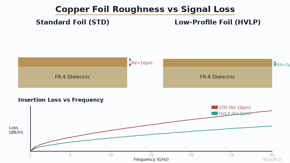
- Copper roughness — The same traces affected by fiber weave Dk variation also experience loss from copper roughness. The combined effect on eye diagrams is worse than either alone.
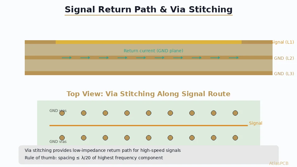
- Glass weave resonance + via stubs — If the fiber weave resonance frequency coincides with via stub resonance, the combined insertion loss null can be severe.
- Temperature variation — Glass and resin have different thermal coefficients of Dk. As temperature changes during operation, the Dk contrast shifts, modifying the skew.
Comprehensive [high-speed design]/blog/high-speed-pcb-design/) must account for all these effects simultaneously through full-channel simulation.
Design Checklist: Managing Fiber Weave Effect
Use this checklist during the design phase to systematically address fiber weave concerns:
Material Selection Phase
- ☐ Identify the maximum data rate and protocol requirements
- ☐ Calculate the allowable intra-pair skew budget (typically ≤ 5% of UI)
- ☐ For data rates ≥ 25 Gbps: specify spread glass (1078, 3313, 2113, or 1067)
- ☐ For data rates ≥ 56 Gbps: consider NE-glass combined with spread glass
- ☐ Verify material availability and lead time with your [PCB manufacturer]/blog/multilayer-fr4-pcb-manufacturer/)
- ☐ Document glass style requirements in the fabrication drawing and stackup specification
Layout and Routing Phase
- ☐ Route critical differential pairs at 7–15° angles to the board edge (which aligns with the warp direction)
- ☐ Avoid 0° and 90° routing for any signal above 10 Gbps on standard glass
- ☐ Keep breakout regions from connectors as short as possible (<1 inch)
- ☐ Match trace lengths within differential pairs to ≤ 1 mil (routing skew separate from fiber weave skew)
- ☐ Add fiber-weave-aware test coupons to the panel border
Simulation and Validation Phase
- ☐ Run 3D EM simulation with actual weave geometry for critical channels
- ☐ Include fiber weave skew in the overall channel timing budget
- ☐ Compare simulation predictions against TDR and VNA measurements on test coupons
- ☐ Verify that production impedance testing captures fiber-weave-scale variation
Production Monitoring Phase
- ☐ Monitor skew measurements on test coupons across production lots
- ☐ Track glass style and resin content consistency with laminate supplier
- ☐ Establish accept/reject criteria for skew that include fiber weave contribution
Material Selection Decision Matrix
Choosing the right material system depends on balancing performance, cost, and availability. Here is a practical decision matrix:
Data rate <10 Gbps (USB 3.0, PCIe Gen2, GbE):
- Standard glass (1080, 2116) is acceptable
- No special routing angle requirements
- Standard FR-4 materials are sufficient
Data rate 10–25 Gbps (PCIe Gen4, 25G Ethernet, USB4):
- Spread glass recommended for critical pairs
- Route at 7–15° angle if using standard glass
- Mid-tier laminates with controlled Dk recommended
Data rate 25–56 Gbps (PCIe Gen5, 56G PAM4):
- Spread glass required
- NE-glass strongly recommended
- Route at non-zero angles even with spread glass
- Low-loss laminate systems required
Data rate ≥ 56 Gbps (112G PAM4, PCIe Gen6, 800G optics):
- NE-glass + spread glass mandatory
- Very-low-loss resin systems (Df ≤ 0.003)
- Full-channel 3D EM simulation including weave effects required
- Consider routing angle optimization even with best materials
For detailed guidance on matching materials to performance requirements, see our comprehensive [PCB material selection guide]/blog/pcb-material-selection-guide/).
Industry Trends and Future Outlook
The fiber weave effect is becoming more critical, not less, as data rates continue to climb:
- 224G SerDes is in development, with UI of approximately 8.9 ps — leaving virtually zero margin for fiber weave skew.
- Co-packaged optics place extremely short but ultra-high-speed channels on organic substrates where fiber weave pitch is comparable to trace length.
- Advanced glass formulations (ultra-low-Dk glass with Dk approaching 4.0) are in qualification to further reduce the glass-resin contrast.
- Non-woven glass alternatives — randomly oriented glass fiber mats and glass-free substrates are being explored for the most extreme applications, though cost and mechanical properties remain challenges.
- AI/ML workloads driving 800G and 1.6T switch platforms are making spread glass + NE-glass the baseline specification for data center infrastructure PCBs.
Conclusion: A Solvable Problem with the Right Approach
The fiber weave effect is a fundamental physical phenomenon inherent to glass-reinforced PCB substrates. It cannot be eliminated by better routing or tighter manufacturing tolerances alone — it requires deliberate material selection, informed routing strategies, and proper simulation.
The good news: with modern spread glass fabrics, NE-glass formulations, and routing angle awareness, the fiber weave effect can be reduced to negligible levels even for the most demanding 112G applications. The key is addressing it early in the design process, during material selection and stackup definition, rather than discovering it during compliance testing.
Partner with a manufacturer who understands high-speed material science. Atlas PCB provides spread glass and NE-glass material options across our multilayer fabrication capabilities, with engineering support to help you select the optimal glass style, stackup, and material system for your performance requirements.
Get a quote for your high-speed PCB project →
About AtlasPCB — We specialize in complex PCB manufacturing for HDI, RF, and high-reliability applications. Explore our impedance-controlled PCB manufacturing . Every order includes free engineering review. Get your quote.
Reviewed by AtlasPCB Engineering Team — IPC-certified manufacturing specialists with 15+ years of production experience in HDI, RF, and high-reliability PCB fabrication. Content based on factory floor data and real customer design reviews.
- fiber weave effect
- signal skew
- high-speed PCB
- differential pairs
- spread glass