· AtlasPCB Engineering · Engineering · 12 min read
High-Speed PCB Laminate Dk/Df Comparison
Compare Dk and Df values of Megtron 6, Rogers 4350B, Isola IS680, and Shengyi laminates for high-speed PCB design.
Why Dk and Df Matter in High-Speed PCB Design
Every signal traveling through a PCB interacts with the dielectric material surrounding the copper traces. Two electrical properties of that dielectric—dielectric constant (Dk) and dissipation factor (Df)—determine how fast signals propagate, how much energy they lose, and whether your design meets its bit-error-rate targets.
Dk (dielectric constant), also called relative permittivity (εr), controls signal velocity and characteristic impedance. A higher Dk slows the signal and requires narrower traces for a given impedance target. More critically, Dk variation across frequency, temperature, and resin content creates impedance discontinuities that generate reflections.
Df (dissipation factor), also called loss tangent (tan δ), quantifies how much electromagnetic energy the material converts to heat as the signal passes through it. Dielectric loss scales linearly with frequency—double the frequency, double the dB/inch loss from the dielectric alone. At 28 Gbps NRZ (fundamental frequency ~14 GHz), dielectric loss dominates total channel loss in traces longer than 3 inches.
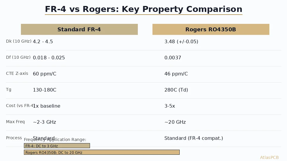
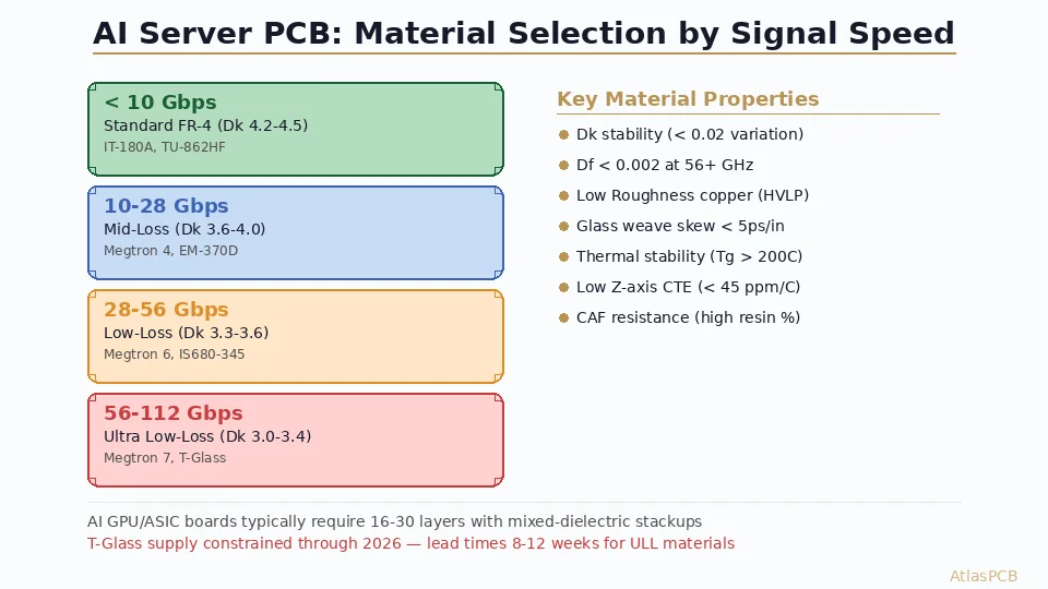
For designs operating at data rates below 5 Gbps, standard FR-4 (Dk ~4.2–4.5, Df ~0.020) often suffices. Above 10 Gbps, low-loss laminates become necessary to maintain adequate eye opening at the receiver. Above 25 Gbps, ultra-low-loss or extremely-low-loss materials are mandatory. Choosing the right material involves balancing electrical performance, thermal reliability, manufacturability, and cost.
This guide compares the most widely specified high-speed laminates from four major manufacturers—Panasonic (Megtron), Rogers, Isola, and Shengyi—with real specification data to help you make informed material selections. For a broader overview of PCB substrate options, see our [PCB materials guide]/blog/pcb-materials-guide/).
Understanding Laminate Loss Categories
The IPC-4101E specification and industry convention classify laminates into loss tiers:
| Category | Df Range (10 GHz) | Typical Applications |
|---|---|---|
| Standard Loss | 0.018–0.025 | Consumer electronics, low-speed digital |
| Mid Loss | 0.010–0.018 | Ethernet 1–5 Gbps, moderate-speed digital |
| Low Loss | 0.005–0.010 | 10–25 Gbps SerDes, 5G mid-band |
| Very Low Loss | 0.003–0.005 | 25–56 Gbps PAM4, mmWave front-end |
| Ultra-Low Loss | 0.001–0.003 | 112 Gbps SerDes, radar, satellite |
These categories are not standardized by IPC but are widely used in supplier literature. The boundaries are approximate. What matters is matching the material’s loss performance to your channel loss budget.
Comprehensive Dk/Df Comparison Table
The following table presents manufacturer-specified typical values. All Dk/Df values are measured at 10 GHz using the manufacturer’s stated test method unless noted otherwise.
| Laminate | Manufacturer | Dk (10 GHz) | Df (10 GHz) | Tg (°C) | Td (°C) | CTE-z (%/°C) | Cost Index |
|---|---|---|---|---|---|---|---|
| FR-4 Standard (e.g., S1141) | Shengyi | 4.25 | 0.019 | 150 | 310 | 3.5 | 1.0× |
| FR-4 Mid-Loss (e.g., IT-180A) | ITEQ | 4.02 | 0.013 | 175 | 340 | 2.8 | 1.3× |
| S1000-2M | Shengyi | 3.90 | 0.008 | 200 | 360 | 2.5 | 1.8× |
| Megtron 4 (R-5775) | Panasonic | 3.80 | 0.005 | 200 | 390 | 2.5 | 2.5× |
| IS680 | Isola | 3.45 | 0.0030 | 200 | 360 | 2.8 | 3.5× |
| Megtron 6 (R-5775K) | Panasonic | 3.71 | 0.002 | 200 | 400 | 2.4 | 4.0× |
| Megtron 7 (R-5785) | Panasonic | 3.60 | 0.0015 | 220 | 410 | 2.2 | 5.0× |
| RO4350B | Rogers | 3.48 | 0.0037 | >280 | N/A | 2.4 | 4.5× |
| RO4003C | Rogers | 3.38 | 0.0027 | >280 | N/A | 2.4 | 4.0× |
| RO3003 | Rogers | 3.00 | 0.0013 | N/A | N/A | 2.4 | 6.0× |
| TU-872 LK | TUC | 3.80 | 0.0035 | 210 | 380 | 2.6 | 3.0× |
Notes on the cost index: Values are normalized to standard FR-4. Actual pricing depends on volume, thickness, panel size, and regional supply. Rogers materials carry a premium partly due to smaller panel sizes (18”×12” vs 18”×24” for Megtron).
Deep Dive: Megtron Series (Panasonic)
Megtron 4 (R-5775)
Megtron 4 is a low-loss modified PPO/epoxy blend that serves as a cost-effective step up from mid-loss FR-4. Its Df of 0.005 at 10 GHz makes it suitable for 10 Gbps–16 Gbps applications. It processes like standard FR-4—same drill parameters, same lamination cycle, same plating chemistry—which is its primary advantage. Many fabricators keep Megtron 4 in stock.
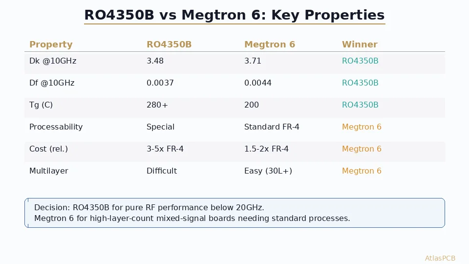
Megtron 6 (R-5775K)
Megtron 6 is the industry workhorse for high-speed digital designs. With Df 0.002 at 10 GHz, it supports data rates from 25 Gbps NRZ through 56 Gbps PAM4 in typical backplane and server applications. Key characteristics:
- Dk stability: Dk varies less than ±0.05 across the 1–20 GHz range, essential for broadband impedance control
- Low moisture absorption: <0.1%, preventing Dk shift in humid environments
- Thermal reliability: Tg 200°C, Td 400°C, T288 >60 minutes—passes all lead-free assembly profiles
- Processing: Compatible with standard FR-4 fabrication lines; no special drill bits or lamination equipment required
- Prepreg options: Multiple resin contents (47%, 54%, 60%) allow flexible stackup tuning
Megtron 6 pairs well with standard FR-4 in hybrid stackups. Route 56 Gbps PAM4 signals on Megtron 6 layers, power/ground on FR-4, and save 30–40% compared to an all-Megtron 6 build. For more on this approach, see our guide to [PCB hybrid stackup Rogers FR4]/blog/pcb-hybrid-stackup-rogers-fr4/).
Megtron 7 (R-5785)
Megtron 7 pushes Df down to 0.0015 at 10 GHz, targeting 112 Gbps PAM4 applications. Its extremely low and flat Df curve makes it suitable for channels exceeding 30 inches. Availability is more limited than Megtron 6, and pricing is roughly 25% higher. Fabrication still follows standard processes, which differentiates the Megtron line from PTFE-based alternatives.
Deep Dive: Rogers Laminates
RO4350B
Rogers RO4350B is a thermoset ceramic-filled hydrocarbon laminate. It dominates the RF and microwave PCB market from 1 GHz through 40 GHz. Its properties include:
- Dk 3.48 ± 0.05 at 10 GHz: Tight tolerance enables precision impedance matching
- Df 0.0037 at 10 GHz: Lower than most epoxy systems but higher than Megtron 6
- Tg >280°C: Exceptional thermal stability—no glass transition concerns during reflow
- CTE-matched to copper: Z-axis CTE of 32 ppm/°C (below Tg), reducing barrel cracking risk
- Lead-free compatible: Withstands 260°C reflow profiles without degradation
RO4350B processes on standard FR-4 equipment—no special PTFE handling required. This is a major advantage over RO3000 series and older PTFE laminates that need sodium-naphthalene surface preparation for plating adhesion.
The primary limitation is panel size. Rogers laminates are available in 12”×18” and 18”×24” panels (material-dependent), while Megtron and FR-4 are available in 18”×24” and 21”×24”. This impacts panelization efficiency and per-unit cost. Review our [PCB panelization guide]/blog/pcb-panelization-guide/) for optimization strategies.
For a detailed comparison with standard FR-4, see our article on [Rogers 4350B vs FR4]/blog/rogers-4350b-vs-fr4/).
RO4003C
RO4003C offers Dk 3.38 and Df 0.0027 at 10 GHz—lower loss than RO4350B—but is not UL 94 V-0 rated (it is UL 94 HB). This limits its use in applications requiring flame-retardant certification. For RF designs where UL rating is not mandated (test equipment, military with waivers), RO4003C provides excellent performance at slightly lower cost than RO4350B.
RO3003
RO3003 is a ceramic-filled PTFE laminate with Df 0.0013 at 10 GHz—among the lowest available. It targets phased-array radar, satellite communications, and mmWave 5G antenna applications above 30 GHz. PTFE processing requirements (plasma treatment for via desmear, sodium etch for adhesion promotion) add fabrication cost and limit the number of qualified suppliers.
Deep Dive: Isola IS680
Isola IS680 is a polyphenylene oxide (PPO)-based laminate that competes directly with Megtron 6. Its specifications are compelling:
- Dk 3.45 at 10 GHz: Lower than Megtron 6 (3.71), allowing slightly wider traces for the same impedance
- Df 0.0030 at 10 GHz: Between Megtron 4 and Megtron 6
- Tg 200°C, Td 360°C: Adequate for lead-free assembly
- CAF resistance: Excellent, rated for 100V bias at 85°C/85% RH for 1000 hours
IS680’s Df of 0.003 positions it as a very-low-loss material—suitable for 25 Gbps designs but borderline for 56 Gbps PAM4 over long traces. Where IS680 excels is Dk stability: the dielectric constant varies less than 2% from 1 GHz to 20 GHz, which simplifies broadband impedance modeling.
Isola also offers IS680 AG (a lower-cost variant with slightly higher Df) and the newer Astra MT77 with Df 0.0017 at 10 GHz, positioning it against Megtron 6 and 7.
Deep Dive: Shengyi S1000-2M
Shengyi Technology, based in Dongguan, China, is the world’s largest laminate manufacturer by volume. Their S1000-2M targets the mid-to-low-loss segment:
- Dk 3.90 at 10 GHz: Higher than Western competitors, resulting in slightly slower propagation
- Df 0.008 at 10 GHz: Positions it between mid-loss and low-loss categories
- Tg 200°C, Td 360°C: Good thermal reliability
- Cost advantage: 30–50% less expensive than Megtron 4 at equivalent constructions
S1000-2M is well-suited for cost-sensitive 10 Gbps designs—network switches, storage controllers, and consumer WiFi 6E routers. For designs requiring Df below 0.005, Shengyi offers the S1000-2ME (Df ~0.004) and the newer SyTec series targeting ultra-low-loss applications.
The primary trade-off with Shengyi materials is supply chain qualification. Many North American and European OEMs have not yet qualified Shengyi materials, though this is changing as Shengyi invests in UL certifications and global distribution.
How to Select the Right Laminate
Step 1: Define the Channel Loss Budget
Start with the receiver’s sensitivity. Most modern SerDes specify a maximum channel insertion loss (IL) at the Nyquist frequency. For example:
- PCIe 5.0 (32 GT/s NRZ): –36 dB max IL at 16 GHz
- 100GBASE-KR4 (25.78 Gbps NRZ): –33 dB max IL at 12.89 GHz
- 400GBASE-KR8 (56 Gbps PAM4): –30 dB max IL at 14 GHz
Step 2: Model the Channel
Use a 2D field solver (Polar SI9000, Ansys 2D Extractor) to compute per-unit-length loss for candidate materials. Total insertion loss includes:
- Dielectric loss: Proportional to Df × frequency. Dominates at higher frequencies.
- Conductor loss: Proportional to √frequency (skin effect). Depends on copper roughness and trace geometry.
- Via transition loss: Typically 0.3–1.0 dB per via pair, depending on stub length and antipad design.
Step 3: Consider Cost and Manufacturability
Don’t over-specify material. If your channel simulation shows –22 dB IL at Nyquist on Megtron 4, there’s no reason to pay for Megtron 6. Conversely, if standard FR-4 yields –40 dB and your budget is –33 dB, no amount of equalization will compensate—you need a better material.
Step 4: Validate with the Fabricator
Material availability varies by fabricator. Before finalizing your material selection, confirm with your manufacturer:
- Do they stock the material or need to order it? (Lead time implications)
- What constructions (core thicknesses, prepreg styles) are available?
- What is their impedance tolerance on this material?
- Have they fabricated the same layer count and technology on this material before?
Upload your Gerbers for a free engineering review and our engineers will validate your material selection against our fabrication capabilities.
Dk/Df Measurement Methods and Why They Matter
Published Dk/Df values depend heavily on the test method used. The same material can show different values depending on the technique:
| Test Method | IPC Reference | Frequency Range | Notes |
|---|---|---|---|
| Stripline resonator | IPC-TM-650 2.5.5.5 | 1–15 GHz | Industry standard, good correlation to PCB structures |
| Split-post dielectric resonator | IPC-TM-650 2.5.5.13 | 1–20 GHz | Non-destructive, suitable for incoming QC |
| Balanced disk resonator | — | 1–40 GHz | Used by some Rogers datasheets |
| Microstrip ring resonator | — | 0.5–20 GHz | Includes conductor loss artifacts, tends to show higher Df |
| Bereskin method (clamped stripline) | IPC-TM-650 2.5.5.5.1 | 1–15 GHz | Common alternative to full stripline build |
When comparing materials across manufacturers, always check that the same test method was used. A 0.001 Df difference between two datasheets could disappear—or double—when measured by the same lab using the same technique.
Copper Roughness: The Hidden Variable
No discussion of high-speed material selection is complete without addressing copper roughness. At frequencies above 5 GHz, surface roughness on the copper-dielectric interface increases conductor loss significantly through the Hammerstad, Huray, or Cannonball-Huray models.
| Copper Type | Rz (µm) | Added Loss at 10 GHz |
|---|---|---|
| Standard ED (STD) | 8–12 | Baseline |
| Reverse-Treated (RTF) | 5–8 | –15% vs STD |
| Very Low Profile (VLP) | 2–4 | –30% vs STD |
| Hyper Very Low Profile (HVLP) | 1–2 | –40% vs STD |
Choosing Megtron 6 with standard roughness copper negates much of the material’s low-loss advantage. Always specify VLP or HVLP copper foil with very-low-loss and ultra-low-loss laminates. The cost adder for HVLP copper is typically 10–15% of the base laminate cost—far less than upgrading to the next material tier.
For a deeper discussion of how copper selection interacts with material choice, see our [high-frequency PCB substrate selection guide]/blog/high-frequency-pcb-substrate-selection-dk-df/).
Hybrid Stackup Strategies
Cost-optimizing a high-speed design often means using different materials for different layers within the same PCB stackup. Common hybrid approaches include:
Sequential Lamination Hybrid
Place Megtron 6 or Rogers cores at the outer signal layers where high-speed traces route, and standard FR-4 cores in the inner layers for power planes and low-speed signals. This reduces material cost by 30–50% versus a full Megtron 6 build.
Key constraint: The fabricator must manage CTE mismatch between materials during lamination. Dk discontinuity at layer transitions also creates minor impedance steps that should be modeled.
Rogers + FR-4 Hybrid
For mixed RF/digital designs—common in 5G small cells, automotive radar, and IoT gateways—route RF traces on a Rogers core bonded to FR-4 cores using a compatible prepreg (e.g., Rogers 4450F or Isola 185HR). This approach is detailed in our [PCB hybrid stackup Rogers FR4]/blog/pcb-hybrid-stackup-rogers-fr4/) article.
Thermal Considerations
High-speed materials must survive lead-free reflow (peak 260°C for SAC305 solder). Key thermal parameters:
- Tg (glass transition temperature): Below Tg, the material is rigid; above Tg, the Z-axis CTE increases dramatically (3–5× typical). Higher Tg delays this transition.
- Td (decomposition temperature): The temperature at which the resin loses 5% of its weight. Materials with Td <340°C may not survive multiple reflow cycles.
- T288 / T300: Time to delamination at 288°C or 300°C. Must exceed the total thermal exposure during assembly (typically >5 minutes cumulative).
Rogers thermoset materials (RO4000 series) excel here with Tg >280°C, effectively eliminating the glass-transition concern entirely.
Real-World Application Matrix
| Application | Data Rate | Recommended Material | Rationale |
|---|---|---|---|
| Consumer WiFi 6E router | 2.5–5 Gbps | Mid-loss FR-4 or S1000-2M | Cost-driven, short traces |
| Enterprise Ethernet switch | 25 Gbps NRZ | Megtron 4 or IS680 | Moderate loss budget, 6–10” traces |
| Data center switch (51.2T) | 112 Gbps PAM4 | Megtron 6 or Megtron 7 | Tight loss budget, long channels |
| 5G mmWave antenna | 28/39 GHz | RO4350B or RO3003 | Precise Dk, minimal dielectric loss |
| Automotive radar (77 GHz) | — | RO3003 or RO3035 | Ultra-low loss at mmWave, tight Dk tolerance |
| Backplane (OCP Open Rack) | 56 Gbps PAM4 | Megtron 6 + HVLP copper | 20–30” channels, extreme loss sensitivity |
Conclusion
Selecting the right high-speed laminate requires matching the material’s Dk and Df performance to your channel’s loss budget—not simply choosing the lowest-loss option available. For most designs between 10 and 56 Gbps, the decision comes down to Megtron 4 (cost-effective low-loss), Megtron 6 (ultra-low-loss workhorse), or IS680 (PPO alternative with excellent Dk stability). For RF and mmWave applications above 10 GHz, Rogers RO4350B and RO4003C remain the standard, with RO3003 for the most demanding frequencies. Shengyi S1000-2M offers compelling value for cost-sensitive designs up to 10 Gbps.
Regardless of which material you select, always validate your choice with channel simulation, confirm availability with your fabricator, and specify appropriate copper roughness. The laminate is only one component of the total loss equation.
Ready to validate your material selection? Upload your Gerbers for a free engineering review — our signal integrity engineers will review your stackup and recommend the optimal laminate for your performance and cost targets.
Further Reading
- [mmWave PCB Material Selection: Rogers vs Megtron vs LCP for 5G and 6G Applications]/blog/mmwave-pcb-material-selection-rogers-megtron-lcp-5g-6g/)
- [Rogers PCB Fabrication: Material Sourcing, Lead Times & Quality Control]/blog/rogers-pcb-fabrication/)
- [RF PCB Material Selection for Automotive Radar: Rogers vs PTFE Performance Analysis at 77-81 GHz]/blog/automotive-radar-pcb-materials-rogers-ptfe-analysis/)
- [PCB Design for GaN and SiC Power Devices: Thermal Management, Layout Rules, and Material Selection]/blog/pcb-design-gan-sic-power-devices-thermal-layout/)
- [PCB Panelization and Array Design: V-Score vs Tab Routing, DFM Rules, and Cost Optimization]/blog/pcb-panelization-v-score-tab-routing-dfm-cost-optimization/)
- Material Options & Capabilities
About AtlasPCB — We specialize in complex PCB manufacturing for HDI, RF, and high-reliability applications. Explore our RF and high-frequency PCB services, or get an impedance-controlled PCB manufacturing . Every order includes free engineering review. Get your quote.
Reviewed by AtlasPCB Engineering Team — IPC-certified manufacturing specialists with 15+ years of production experience in HDI, RF, and high-reliability PCB fabrication. Content based on factory floor data and real customer design reviews.
- dk-df
- high-speed-laminates
- megtron
- rogers
- isola
- material-selection