· AtlasPCB Engineering · Engineering · 14 min read
Hybrid PCB Stackup Design: Combining Rogers and FR4 for Cost-Effective RF Performance
Learn how hybrid PCB stackups combining Rogers high-frequency laminates with FR4 deliver excellent RF performance at a fraction of the cost of all-Rogers designs. This guide covers material selection, lamination challenges, CTE management, and practical design rules.
Hybrid PCB Stackup Design: Combining Rogers and FR4 for Cost-Effective RF Performance
Designing RF and microwave circuits demands low-loss, tightly controlled dielectric materials. Rogers laminates have long been the gold standard for high-frequency signal integrity — but building an entire multilayer board from Rogers material is expensive and often unnecessary. Only the layers carrying RF traces truly need that level of performance. The rest of the board — power planes, ground reference layers, and digital signal routes — can use standard FR4 without any measurable degradation in system performance.
This is the core principle behind hybrid PCB stackups: strategically placing high-frequency laminates where they matter and FR4 everywhere else. The result is a board that performs like a premium RF design but costs a fraction of an all-Rogers construction.
In this guide, we’ll walk through the engineering rationale, material selection, lamination considerations, CTE mismatch management, and practical design rules that make hybrid stackups work reliably in production. Whether you’re designing 5G front-end modules, automotive radar, or satellite communication hardware, these principles apply.
Why Hybrid Stackups Make Engineering and Economic Sense
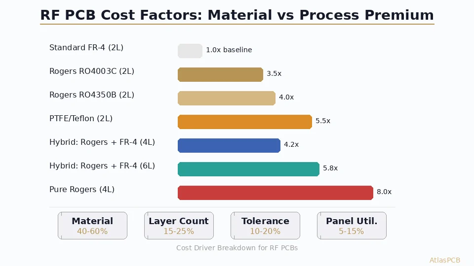
The cost difference between Rogers and FR4 is substantial. A standard 0.060″ panel of Rogers RO4350B costs roughly 8–12× more per square foot than equivalent FR4 laminate. For a typical 8-layer design, if only two layers carry RF signals, building the entire stack from Rogers means paying premium pricing for six layers that gain nothing from the material’s superior dielectric properties.
Consider a practical example: an 8-layer 5G small-cell radio board. The design requires two microstrip RF layers for the PA output matching network and the LNA input, operating at 3.5 GHz. The remaining layers handle digital control signals, power distribution, and grounding. In an all-Rogers construction, this board might cost $180–250 per unit at moderate volume. A hybrid design — RO4350B on layers 1 and 8, FR4 for the internal layers — brings the unit cost down to $60–90, a reduction of 60–70%.
But cost isn’t the only advantage. FR4 actually offers some practical benefits over Rogers in certain aspects:
- Better mechanical rigidity — FR4’s glass-reinforced epoxy provides superior structural support, particularly important for connectorized assemblies and boards with heavy components
- Wider supplier availability — FR4 prepregs and cores are universally stocked; specialized Rogers bondply may have longer lead times
- Established process compatibility — Every PCB fabricator in the world processes FR4 daily; not all are qualified for full-Rogers multilayer lamination
The engineering case is clear: use premium materials where they deliver measurable performance gains, and use cost-effective materials everywhere else. For a deeper comparison of the two base materials, see our detailed guide on [Rogers 4350B vs FR4]/blog/rogers-4350b-vs-fr4/).
Selecting the Right Rogers Material for Hybrid Designs
Not all Rogers laminates are equally suited for hybrid stackups. The critical factor is lamination compatibility — can the Rogers material bond reliably with FR4 prepregs using standard multilayer processing parameters?
RO4000 Series: The Hybrid-Optimized Choice
Rogers RO4000 series materials were specifically engineered for compatibility with FR4 manufacturing processes:
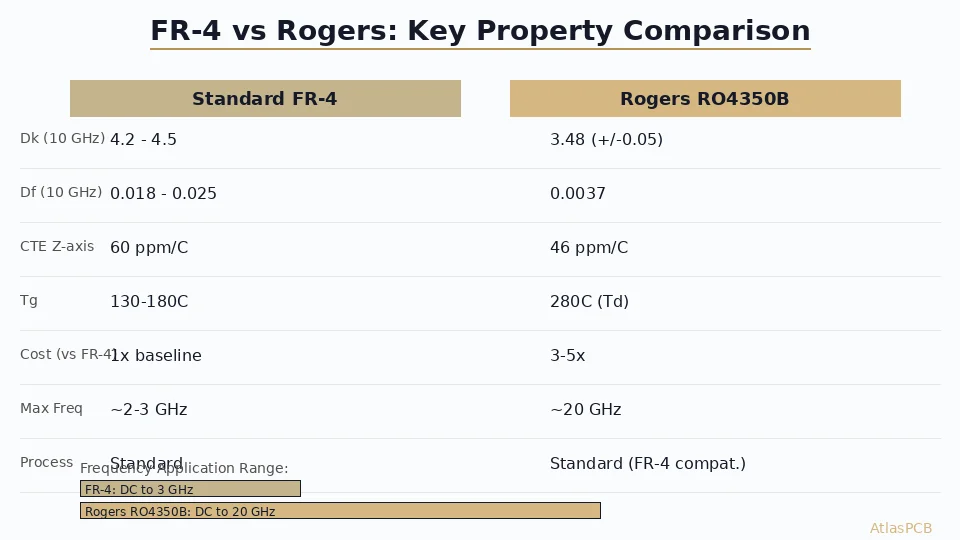
| Property | RO4350B | RO4003C | Standard FR4 |
|---|---|---|---|
| Dk (10 GHz) | 3.48 ± 0.05 | 3.38 ± 0.05 | 4.2–4.5 |
| Loss tangent (10 GHz) | 0.0037 | 0.0027 | 0.018–0.025 |
| CTE (Z-axis, below Tg) | 32 ppm/°C | 46 ppm/°C | 50–70 ppm/°C |
| Tg | >280°C | >280°C | 130–180°C |
| Lamination temp | 185°C | 185°C | 175–190°C |
| Td (decomposition) | 390°C | 350°C | 300–340°C |
The key advantage: RO4350B and RO4003C use a thermoset hydrocarbon/ceramic resin system that cures at temperatures compatible with standard FR4 epoxy prepregs. This means you can laminate a hybrid stackup in a single press cycle using the same temperature and pressure profiles your fabricator already uses for FR4.
PTFE-Based Materials: Proceed with Caution
High-performance PTFE-based laminates like RT/duroid 5880 (Dk = 2.20, loss tangent = 0.0009 at 10 GHz) offer superior electrical performance but present significant hybrid lamination challenges:
- PTFE does not bond well with epoxy prepregs — it requires specialized bonding films like Rogers 2929 bondply or Taconic FastRise
- Lamination temperatures for PTFE bonding (typically 220–260°C) can exceed the Tg of FR4, causing dimensional instability in the FR4 layers
- The extremely low CTE of PTFE (X/Y: 16–20 ppm/°C) creates a severe mismatch with FR4 (14–17 ppm/°C X/Y, but 50–70 ppm/°C Z-axis)
If your design demands PTFE performance (e.g., frequencies above 20 GHz where even RO4350B losses become significant), hybrid construction is still possible but requires a fabricator experienced with mixed-dielectric lamination and appropriate bonding materials.
Material Selection Decision Matrix
- Below 10 GHz: RO4350B + FR4 hybrid is ideal. The 0.004 loss tangent is more than adequate.
- 10–20 GHz: RO4003C + FR4 offers slightly lower loss. Consider the total trace length — short traces may tolerate RO4350B.
- Above 20 GHz: Evaluate whether hybrid is viable. PTFE-based laminates may be necessary for long RF paths, but short interconnects can still use RO4000 series.
- Extremely low loss applications: All-Rogers or all-PTFE may be unavoidable for satellite transponders, radio astronomy front ends, or test instrumentation.
Designing the Hybrid Stackup: Layer Assignment and Symmetry
A successful hybrid stackup requires thoughtful layer assignment and attention to mechanical balance. Here’s a systematic approach.
Principle 1: RF Signals on Outer Layers
Place Rogers laminates as the outermost dielectric layers (between layer 1 and 2, and/or between the last two layers). This approach has several advantages:
- Microstrip is the most common RF transmission line topology, and it requires a signal trace on an outer layer referenced to an adjacent ground plane
- Outer-layer Rogers placement avoids burying expensive material in the middle of the stack where it’s harder to control thickness
- Surface-mount RF components connect directly to the Rogers layer without via transitions that add parasitic inductance
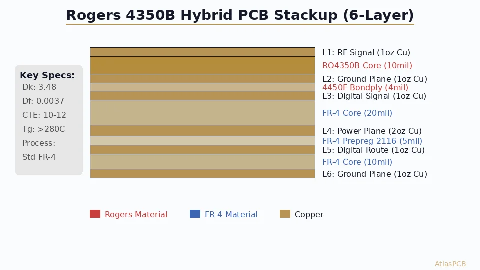
A typical 8-layer hybrid stackup:
Layer 1 (Signal - RF)     ─── RO4350B core (0.010") ───
Layer 2 (Ground)          ─── FR4 prepreg (0.008") ───
Layer 3 (Signal - Digital)─── FR4 core (0.012") ───
Layer 4 (Power)           ─── FR4 prepreg (0.008") ───
Layer 5 (Ground)          ─── FR4 prepreg (0.008") ───
Layer 6 (Signal - Digital)─── FR4 core (0.012") ───
Layer 7 (Ground)          ─── FR4 prepreg (0.008") ───
Layer 8 (Signal - RF)     ─── RO4350B core (0.010") ───
Principle 2: Maintain Stackup Symmetry
A symmetrical stackup — mirrored about the center — is critical for preventing warpage during lamination and thermal cycling. If you use Rogers on the top, use Rogers on the bottom. The material types, thicknesses, and copper weights should mirror each other.
An asymmetrical hybrid stackup will warp because the different CTE values of Rogers and FR4 create unequal stress distribution during cooling from lamination temperature. IPC-6012 Class 2 allows a maximum bow and twist of 0.75% for surface-mount assemblies. A badly asymmetric hybrid design can easily exceed this, making component placement unreliable.
Principle 3: Ground Plane Adjacency
Every RF signal layer should be immediately adjacent to a continuous ground plane. In the stackup above, Layer 1 (RF) is referenced to Layer 2 (Ground), and Layer 8 (RF) is referenced to Layer 7 (Ground). This ensures controlled impedance for microstrip lines and provides a low-inductance return current path.
For stripline RF routing (buried between two ground planes), you would need Rogers material in the internal layers — increasing cost but sometimes necessary for designs requiring shielding from external interference.
For more on stackup design principles, see our comprehensive [PCB stackup design guide]/blog/pcb-stackup-design-guide/).
Managing CTE Mismatch
Coefficient of thermal expansion mismatch is the single largest reliability concern in hybrid stackups. When the board heats up during soldering, rework, or operation, different materials expand at different rates. This creates internal stress that can cause delamination, microcracking, or barrel cracking in plated through-holes.
Z-Axis CTE: The Critical Direction
The most significant CTE mismatch in hybrid stackups occurs along the Z-axis (through the board thickness):
- RO4350B Z-axis CTE: 32 ppm/°C (below Tg)
- FR4 Z-axis CTE: 50–70 ppm/°C (below Tg), 250–300 ppm/°C (above Tg)
- Copper barrel plating: 17 ppm/°C
During a lead-free reflow cycle peaking at 260°C, the FR4 layers expand dramatically in Z while the Rogers layers expand much less. This differential stress concentrates at the material interfaces and at plated through-hole barrels.
Mitigation Strategies
1. Use high-Tg FR4 in hybrid designs. Specifying FR4 with Tg ≥ 170°C (preferably 180°C, such as Isola 370HR or Shengyi S1000-2M) minimizes the duration of the high-CTE regime during reflow. Standard 130°C Tg FR4 should never be used in hybrid stackups.
2. Specify adequate copper plating thickness in through-holes. IPC-6012 Class 3 requires a minimum of 25 µm (1 mil) average copper plating in through-holes. For hybrid stackups, targeting 30–35 µm provides additional margin against barrel cracking from CTE-induced stress.
3. Minimize total board thickness. Thinner boards experience less absolute Z-axis expansion. If your design allows, target 1.2 mm (0.047”) or less total thickness rather than the standard 1.6 mm.
4. Optimize reflow profiles. Work with your assembly house to use the minimum peak temperature and shortest time-above-liquidus that achieves reliable solder joints. Every degree above minimum adds stress to the CTE mismatch interfaces.
Lamination Process Considerations
Single-Cycle vs Sequential Lamination
The most cost-effective hybrid approach uses single-cycle lamination: all layers are stacked and pressed in one operation. This works well when using RO4000 series materials because their cure temperature (185°C) aligns with FR4 epoxy.
Sequential lamination — where the Rogers layers are bonded first, then the FR4 layers are added in a second press cycle — is sometimes necessary for complex designs but doubles the lamination cost and introduces additional registration error.
Prepreg Selection for the Rogers-FR4 Interface
The bonding layer between a Rogers core and an FR4 core is critical. Standard FR4 prepregs (such as Isola 370HR 1080 or 2116 styles) work well for RO4000 series materials. The epoxy in the prepreg flows during lamination and creates a mechanical bond with both the Rogers and FR4 surfaces.
For best adhesion:
- Surface preparation: Rogers cores should be micro-etched (sodium persulfate or equivalent) before layup to promote adhesion
- Prepreg resin content: Use medium-to-high resin content prepregs (≥55% RC) at the hybrid interface to ensure void-free bonding
- Press parameters: Standard FR4 press cycles work, but ensure the heating rate doesn’t exceed 3°C/min to avoid thermal shock at the material interfaces
Registration and Dimensional Stability
Rogers and FR4 materials have different dimensional stability characteristics during lamination. Rogers RO4000 series materials are more dimensionally stable than FR4 (lower moisture absorption, less movement during heating), which means the FR4 layers may shift slightly relative to the Rogers layers during pressing.
To manage this:
- Use registration holes drilled after coupon bonding rather than relying on pre-punched tooling holes in individual layers
- Specify tighter inner-layer registration tolerance (±2 mil or better) in your fabrication notes
- Add registration coupons to the panel for post-lamination verification
Impedance Control in Hybrid Stackups
Controlled impedance is typically the primary reason for using Rogers in the first place. In a hybrid stackup, impedance calculations must account for the actual dielectric properties of each layer.
Key Considerations
Dk accuracy matters more on Rogers layers. Rogers specifies Dk to ±0.05 (e.g., RO4350B: 3.48 ± 0.05 at 10 GHz). FR4 Dk varies more widely (4.2–4.5 typical, depending on resin content and frequency). Since your RF traces are on Rogers layers, the tighter Dk tolerance translates directly to better impedance predictability.
Use frequency-dependent Dk values. Rogers provides Dk data at multiple frequencies. At 1 GHz, RO4350B measures Dk = 3.66; at 10 GHz, it measures 3.48. Using the wrong frequency’s Dk in your impedance calculator will give incorrect trace widths. Always use the Dk value at your signal’s operating frequency.
Account for the prepreg layer at hybrid interfaces. If your RF microstrip’s ground reference plane is on the other side of a hybrid interface (Rogers core + FR4 prepreg), the effective Dk is a weighted combination of both materials based on their thicknesses. Your 2D field solver must model both layers explicitly.
Specify impedance coupons on Rogers layers. Ensure your fabricator builds impedance test coupons using the same Rogers material and stackup as your production traces. Coupons built on FR4 test strips will not reflect the actual impedance of your RF lines.
For detailed guidance on [RF PCB design best practices]/blog/rf-pcb-design-guidelines/), including trace geometry and transition optimization, refer to our dedicated RF guide.
Drill and Via Considerations
Drilling through a hybrid stackup presents unique challenges because the drill bit encounters materials with very different mechanical properties.
Drill Wear and Hole Quality
Rogers RO4000 series materials contain ceramic filler particles that are more abrasive than the glass fibers in FR4. A drill bit transitioning from FR4 into Rogers (or vice versa) experiences a sudden change in cutting resistance. This can cause:
- Nail-heading: The hole entrance in the softer material mushrooms outward
- Rough hole walls: Smear and fiber pullout at the material transition
- Accelerated drill wear: Ceramic filler dulls carbide drill bits faster
Mitigation: Use fresh drill bits with hit counts appropriate for Rogers (typically 30–50% fewer hits per bit compared to FR4-only drilling). Specify entry and backer materials appropriate for mixed-dielectric drilling.
Desmear Process
The desmear process that removes epoxy smear from hole walls after drilling must be calibrated for hybrid stackups. Standard permanganate desmear works well for FR4 but may be less effective on Rogers resin. Plasma desmear is generally preferred for hybrid boards as it removes both FR4 and Rogers resin residues effectively.
Cost Comparison: Hybrid vs All-Rogers vs All-FR4
Here’s a realistic cost comparison for an 8-layer, 100 × 100 mm board at 100-piece quantity:
| Configuration | Material Cost | Processing Premium | Total Unit Cost |
|---|---|---|---|
| All-FR4 (Isola 370HR) | $8–12 | Baseline | $35–50 |
| Hybrid (2× RO4350B + 6× FR4) | $25–35 | +15–20% | $65–95 |
| All-Rogers (RO4350B) | $90–140 | +30–40% | $180–260 |
The hybrid approach delivers roughly 65% savings compared to all-Rogers while maintaining identical RF performance on the signal layers. The processing premium for hybrid is modest because RO4000 series materials are compatible with standard FR4 processing equipment.
Design Rules Summary for Hybrid Stackups
- Use RO4000 series (RO4350B or RO4003C) for FR4 compatibility
- Place Rogers on outer layers for microstrip RF routing
- Maintain stackup symmetry to prevent warpage (mirror material types about center)
- Specify high-Tg FR4 (≥170°C) for internal layers
- Use medium-to-high resin content prepreg at hybrid interfaces
- Design for single-cycle lamination when possible
- Specify impedance coupons on the actual Rogers layer, not FR4
- Use frequency-accurate Dk values in impedance calculations
- Reduce drill hit counts by 30–50% compared to FR4-only boards
- Request plasma desmear rather than permanganate for best hole wall quality
When Hybrid Isn’t the Right Choice
Hybrid stackups aren’t universally superior. Consider all-Rogers in these scenarios:
- Stripline RF routing on multiple internal layers: If three or more layers require Rogers, the cost savings from FR4 on the remaining layers may not justify the added complexity
- Extreme thermal cycling: Applications with repeated -55°C to +125°C cycles (military/space) may see reliability issues at hybrid interfaces over thousands of cycles
- Very thin boards: Below 0.5 mm total thickness, there may not be enough layers to justify hybrid construction
And consider all-FR4 when:
- Frequencies below 2 GHz: Standard FR4 losses are acceptable for many sub-2 GHz applications, especially with short trace lengths
- Cost is the dominant constraint: If the product is highly cost-sensitive and RF performance requirements have margin, FR4 may suffice with careful design
Conclusion
Hybrid PCB stackups represent the pragmatic middle ground between RF performance and manufacturing cost. By placing Rogers laminates only on the layers that carry high-frequency signals and using FR4 for everything else, engineers can capture 90%+ of the performance benefit at 30–40% of the cost of an all-Rogers design.
The keys to success are material selection (RO4000 series for process compatibility), symmetrical stackup design, proper management of CTE mismatch through high-Tg FR4 and adequate plating thickness, and working with a fabricator experienced in mixed-dielectric lamination.
As 5G, automotive radar, and IoT proliferate — all demanding RF performance at consumer-friendly price points — hybrid stackups are becoming a standard tool in the PCB designer’s arsenal rather than an exotic specialty.
Ready to start your project? Upload your Gerbers for a free engineering review, or talk to an engineer about your design requirements.
Further Reading
- [mmWave PCB Material Selection: Rogers vs Megtron vs LCP for 5G and 6G Applications]/blog/mmwave-pcb-material-selection-rogers-megtron-lcp-5g-6g/)
- [Rogers PCB Fabrication: Material Sourcing, Lead Times & Quality Control]/blog/rogers-pcb-fabrication/)
- [RF PCB Material Selection for Automotive Radar: Rogers vs PTFE Performance Analysis at 77-81 GHz]/blog/automotive-radar-pcb-materials-rogers-ptfe-analysis/)
- [Aluminum PCB Thermal Design for High-Power LED and Motor Drivers: Material Selection, Stackup, and DFM Guide]/blog/aluminum-pcb-thermal-design-led-motor-driver/)
- [PCB Design for GaN and SiC Power Devices: Thermal Management, Layout Rules, and Material Selection]/blog/pcb-design-gan-sic-power-devices-thermal-layout/)
- Rigid PCB Manufacturing
About AtlasPCB — We specialize in complex PCB manufacturing for HDI, RF, and high-reliability applications. Explore our RF and high-frequency PCB services, or get an multilayer PCB fabrication up to 30 layers . Every order includes free engineering review. Get your quote.
Reviewed by AtlasPCB Engineering Team — IPC-certified manufacturing specialists with 15+ years of production experience in HDI, RF, and high-reliability PCB fabrication. Content based on factory floor data and real customer design reviews.
- hybrid-stackup
- rogers
- fr4
- rf-pcb
- cost-optimization