· AtlasPCB Engineering · Engineering · 8 min read
NVIDIA HVLP4 Copper Foil Requirements: What Next-Gen AI Server PCBs Demand from Your Fabricator
NVIDIA is driving adoption of HVLP4 ultra-low-profile copper foil for AI server PCBs, creating a widening gap between fabricators who can source it and those who cannot. Technical analysis of why HVLP4 matters for 112G+ SerDes channels, what Rz roughness specifications mean for insertion loss, and how to specify copper foil grade in your PCB stackup.
The Copper Foil Gap That Is Reshaping AI Server PCB Supply Chains
A quiet but consequential shift is occurring in the AI server PCB supply chain: NVIDIA’s newest platform specifications are mandating copper foil grades that most PCB fabricators cannot readily source. As reported by Digitimes in June 2026, the gap between fabricators who have secured HVLP4 supply and those still working with previous-generation foil is widening, creating a de facto tiering of the fabrication ecosystem around AI server qualification.
This is not merely a material specification change — it is a supply chain restructuring that determines which fabricators can participate in the highest-value segment of the PCB market. For hardware engineers designing AI server motherboards, baseboard PCBs, and high-speed backplanes, understanding HVLP4 requirements and your fabricator’s readiness is now a critical path item.
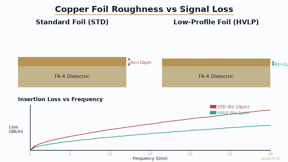
Why Surface Roughness Becomes the Limiting Factor at 112G+
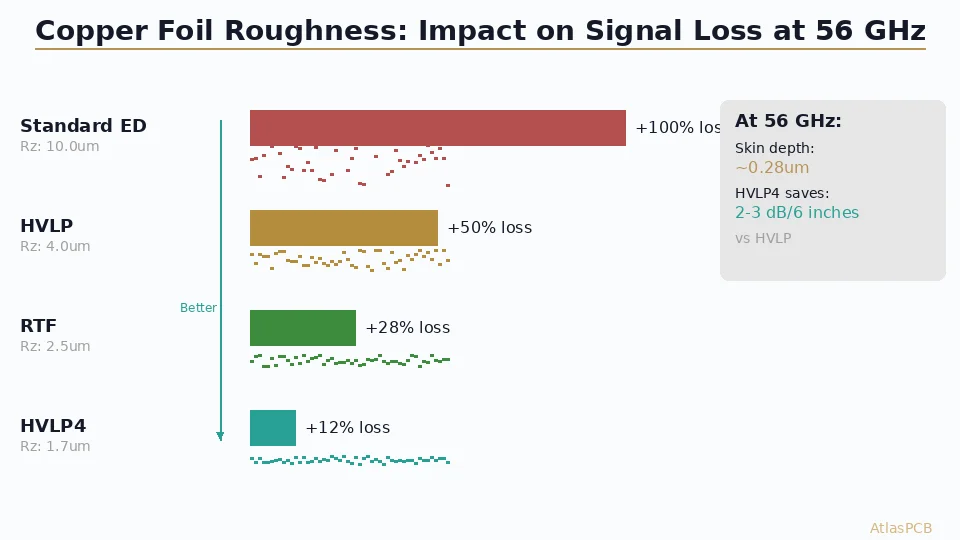
The fundamental physics is straightforward. At high frequencies, current in a conductor concentrates within a thin layer near the surface — the skin effect. At 56 GHz (the Nyquist frequency of 112G PAM4), the skin depth in copper is approximately 0.28um. This means that almost all signal current flows within the outermost 0.3-0.4um of the copper trace cross-section.
When the copper surface has roughness features (peaks and valleys) on the same order as this skin depth, the current path becomes longer than the geometric trace length. The effective resistivity of the conductor increases because current must navigate around and through surface texture rather than flowing along a smooth plane. This additional loss is frequency-dependent — it barely matters at 1 GHz but becomes the dominant loss mechanism above 30 GHz.
The relationship between roughness and loss is well-characterized by the Hammerstad-Jensen model and its modern corrections. For a microstrip trace with Rz roughness, the conductor loss increase versus a perfectly smooth conductor is approximately:
- Rz = 8um (standard ED): +80-120% excess loss at 56 GHz
- Rz = 4um (HVLP): +40-60% excess loss at 56 GHz
- Rz = 2um (RTF/HVLP3): +20-30% excess loss at 56 GHz
- Rz = 1.5um (HVLP4): +10-15% excess loss at 56 GHz
For a practical example: a 6-inch stripline trace on standard HVLP material (Megtron 6 with HVLP foil, Rz ~4um) has approximately 18 dB insertion loss at 56 GHz. The same trace on HVLP4 foil recovers approximately 2.5 dB, bringing total loss to 15.5 dB. For a 112G PAM4 channel with a receiver sensitivity requiring better than -20 dB, that 2.5 dB margin recovery can mean the difference between a compliant channel and a failing one.
HIGH-SPEED SIGNAL INTEGRITY
Low-Loss Stackups with Premium Copper Foil
AtlasPCB sources RTF and HVLP copper foil grades from qualified suppliers. We work with your SI engineer to match foil roughness to your channel loss budget.
Discuss Your Stackup ›HVLP4 Supply Chain Reality: Who Has It and Who Does Not
The copper foil supply chain for PCB fabrication is dominated by a handful of manufacturers. For HVLP4-grade material specifically, the qualified supplier list is even shorter:
| Supplier | Product | Rz (matte side) | Status |
|---|---|---|---|
| Mitsui Mining | BHY-22T-HA | 1.5-1.8um | Production, limited allocation |
| Circuit Foil | HTE-4 | 1.6-2.0um | Production, Europe/Asia |
| Nan Ya Plastics | HVLP-4 Series | 1.7-2.0um | Ramping, Taiwan priority |
| Furukawa Electric | GTS-MP4 | 1.5-1.7um | Qualification phase |
The challenge for PCB fabricators is not just procurement — it is process qualification. HVLP4 foil has fundamentally different lamination characteristics compared to standard or even HVLP foil. The ultra-smooth matte side provides less mechanical interlocking with the prepreg resin during lamination, resulting in lower peel strength (typically 3-4 lb/inch versus 5-7 lb/inch for HVLP). This requires adjusted lamination pressure profiles, modified surface treatment processes, and updated IPC acceptance criteria for peel testing.
Fabricators who invested early in HVLP4 qualification (typically large Taiwanese and Japanese shops serving NVIDIA directly) have 12-18 months of process data and optimized lamination recipes. Fabricators attempting to qualify HVLP4 today face a 3-6 month qualification cycle before they can offer production volumes, plus material procurement lead times that have stretched to 8-12 weeks due to allocation priority going to established high-volume customers.
How to Specify Copper Foil Grade in Your Stackup
Many PCB designers specify laminate material (Megtron 6, Tachyon 100G, etc.) without explicitly calling out the copper foil grade. This was acceptable when the foil choice had minimal performance impact, but at 56 GHz+ frequencies, the foil specification matters as much as the dielectric selection.
Your stackup documentation should explicitly state:
1. Foil grade per layer. Not all layers need HVLP4. Power and ground planes carrying only DC current can use standard HVLP to reduce cost. Specify HVLP4 only on layers carrying high-speed differential pairs.
Example stackup callout:
- L1 (Signal, 56G): 1/2oz HVLP4, Rz max 2.0um
- L2 (Ground): 1oz HVLP, standard
- L3 (Signal, 56G): 1/3oz HVLP4, Rz max 2.0um
- L4 (Power): 2oz standard ED
2. Roughness specification with measurement method. Specify Rz (ten-point average roughness) measured per IPC-TM-650 Method 2.2.17. Stating “HVLP4” without a numerical Rz limit leaves ambiguity because different suppliers have slightly different roughness within the HVLP4 category.
3. Peel strength acceptance criteria. Because HVLP4 has lower adhesion than standard foil, your acceptance criteria must reflect achievable values. Specify minimum peel strength per IPC-TM-650 2.4.8 with the actual tested value from your fabricator’s qualification data — typically 3.0 lb/inch minimum after thermal stress, compared to the standard 4.0 lb/inch requirement for conventional foil.
4. Insertion loss test requirement. For critical channels, specify a maximum insertion loss per IPC-TM-650 2.5.5.13 on a test coupon with defined geometry. This validates the combined effect of foil roughness and dielectric loss on your actual production panels.
ADVANCED MATERIALS
RTF and Low-Profile Foil Available for High-Speed Builds
AtlasPCB works with premium copper foil suppliers to support designs requiring low-roughness conductors. We specify and verify foil grade per your channel requirements.
Upload Your Design ›The Broader AI Infrastructure Material Pressure
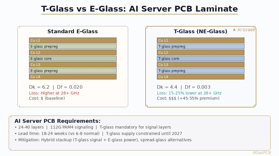
The HVLP4 copper foil situation is one piece of a larger material constraint pattern affecting AI server PCB fabrication. The combination of specialized dielectrics (very-low-loss resins), ultra-low-profile foils, and high-frequency-optimized glass weave creates a “perfect storm” of material procurement challenges:
T-glass fiber cloth — needed for uniform dielectric constant in low-loss laminates — remains in chronic short supply as AI server demand consumes available capacity. T-glass provides more uniform glass-resin distribution than standard E-glass, reducing fiber-weave-related impedance variation.
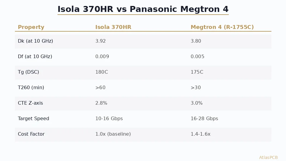
Very-low-loss resin systems (Df below 0.003 at 10 GHz) — materials like Panasonic Megtron 7 (R-5785N) and Isola Tachyon 100G — have extended lead times as laminate manufacturers prioritize allocation for tier-1 AI server programs.
ABF build-up materials — while primarily consumed by IC substrate manufacturing (see: AT&S expansion), the same materials are used in advanced HDI PCBs that interface with high-end BGA packages, creating allocation competition.
For hardware engineering teams planning AI server or HPC platform designs, the material procurement strategy needs to start simultaneously with electrical design — not after the layout is complete. Engaging your fabricator during schematic/stackup planning allows them to verify material availability and suggest equivalent alternatives if your first-choice materials have extended lead times.
Design Implications Beyond Material Choice
The move to HVLP4 and ultra-low-loss materials has cascading effects on PCB design practices that go beyond simply specifying a different material code:
Trace geometry optimization. With lower conductor loss from smooth foil, the relative contribution of dielectric loss increases. This makes trace width optimization more impactful — wider traces have less conductor loss per unit length, and the smooth foil surface means less diminishing-returns from width increases at high frequency.
Via transition design. The insertion loss budget saved by HVLP4 foil can be “spent” on slightly longer via transitions or relaxed backdrill tolerances. Conversely, if your channel is marginal even with HVLP4, every via transition must be optimized (anti-pad sizing, back-drilling, via stub minimization).
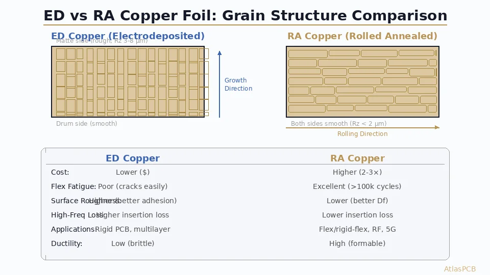
Stackup hybrid approaches. The cost premium of HVLP4 makes full-board specification expensive. Best practice is a hybrid approach: HVLP4 on the 2-4 signal layers carrying your highest-speed channels, standard HVLP on lower-speed signal layers, and standard ED on power/ground planes. This requires explicit per-layer foil callouts in your fabrication notes.
ATLASPCB
AI Server PCBs with Premium Signal Integrity Materials
From Megtron 6 to low-loss hybrid stackups with RTF copper, we build the complex multilayer boards that AI infrastructure demands. Tell us your frequency target and channel length — we will recommend the right material stack.
Get Stackup Quote ›Related Reading:
About AtlasPCB — We specialize in complex PCB manufacturing for HDI, RF, and high-reliability applications. Explore our impedance-controlled PCB manufacturing . Every order includes free engineering review. Get your quote.
Reviewed by AtlasPCB Engineering Team — IPC-certified manufacturing specialists with 15+ years of production experience in HDI, RF, and high-reliability PCB fabrication. Content based on factory floor data and real customer design reviews.
- HVLP4 copper foil
- AI server PCB
- signal integrity
- insertion loss
- 112G SerDes
- NVIDIA
- PCB materials