· AtlasPCB Engineering · Engineering · 10 min read
FR-4 vs Rogers PCB for UWB Radar: 6-9 GHz Material Selection and Stackup Design
Choosing between FR-4 and Rogers 4350B for ultra-wideband radar modules operating at 6-9 GHz. Insertion loss data, impedance stability, and hybrid stackup strategies with real fabrication parameters from our production line.
Quick Answer
For UWB radar modules operating at 6-9 GHz, Rogers 4350B delivers 3-4x lower insertion loss than standard FR-4 and maintains Dk stability within +/-0.05 across the full band. Use Rogers for antenna and RF front-end layers; FR-4 is acceptable for digital baseband layers in a hybrid stackup.
Quick Answer: FR-4 vs Rogers for UWB Radar
| Parameter | FR-4 (Standard) | Rogers 4350B | Impact at 6-9 GHz |
|---|---|---|---|
| Dk | 4.2-4.5 (+/-0.3) | 3.48 (+/-0.05) | Rogers: predictable impedance |
| Df (loss tangent) | 0.018-0.022 | 0.0037 | Rogers: 3-4x less signal loss |
| Insertion loss at 7.5 GHz | ~0.37 dB/inch | ~0.12 dB/inch | Rogers wins by 0.25 dB/inch |
| Impedance stability vs temp | +/-8% (25-85C) | +/-2% (25-85C) | Rogers: automotive-grade stability |
| Cost (4L, 50x50mm, qty 50) | $8-12/board | $35-55/board | FR-4: 3-5x cheaper |
| Recommended for | Digital baseband | Antenna + RF front-end | Hybrid stackup optimal |
Bottom line: If your UWB radar link budget has less than 3 dB total margin for PCB losses, Rogers 4350B is mandatory on the RF layers. If you have generous margin and short traces (under 15mm), carefully characterized high-frequency FR-4 variants like Panasonic Megtron 4 can work for cost-sensitive consumer applications.
Why UWB Radar Pushes FR-4 Beyond Its Limits
Ultra-wideband radar operates across a remarkably wide bandwidth — typically 500 MHz to 2 GHz of instantaneous bandwidth centered around 6.5 GHz (channel 5) or 8.0 GHz (channel 9) per IEEE 802.15.4z. This combination of moderately high frequency and wide bandwidth creates two problems that standard FR-4 cannot reliably solve.
The first issue is frequency-dependent dielectric constant. FR-4 exhibits significant Dk dispersion across the 6-9 GHz range, meaning that a 50-ohm microstrip line designed for 6.5 GHz will present 47-48 ohms at 8 GHz and 51-52 ohms at 5.5 GHz. For narrowband systems this might be tolerable, but UWB radar relies on pulse fidelity across the entire band — impedance ripple directly translates to pulse distortion and degraded range resolution.
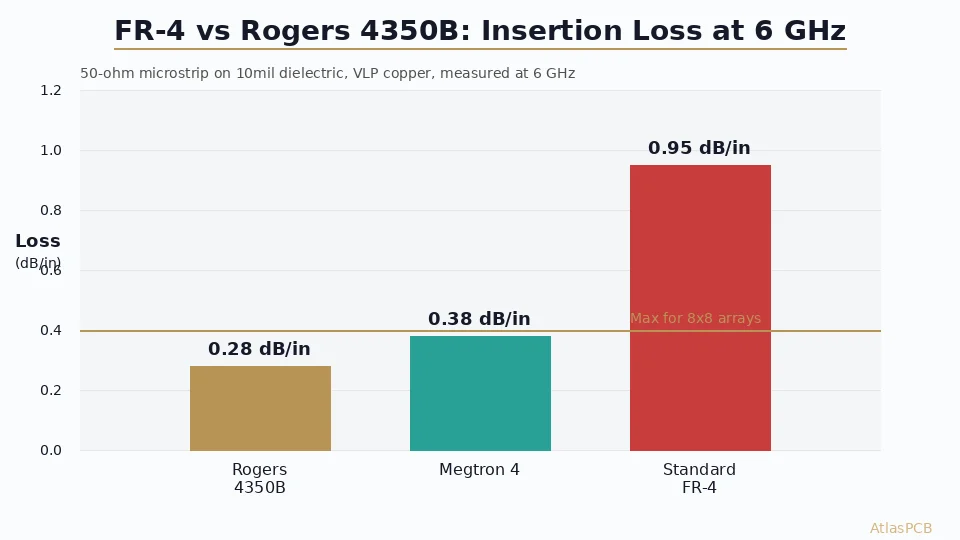
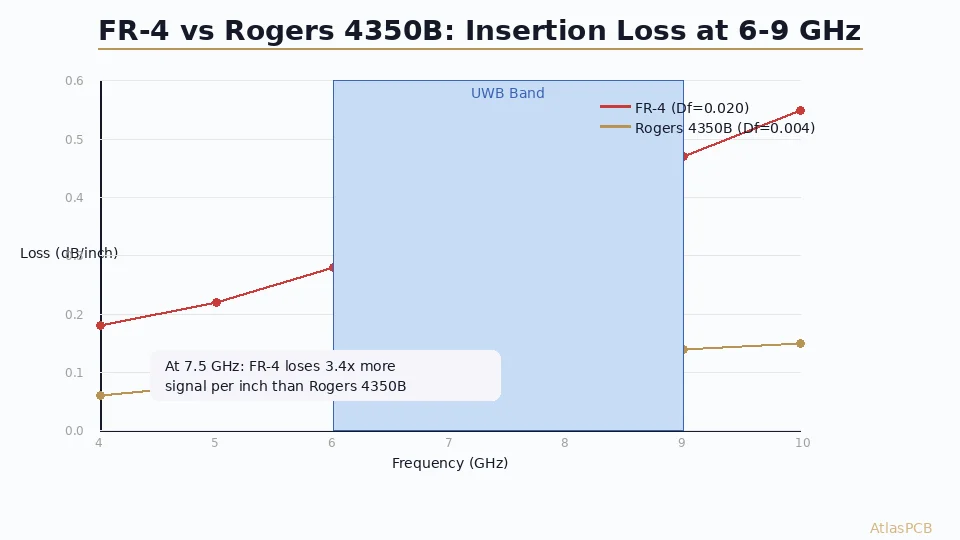
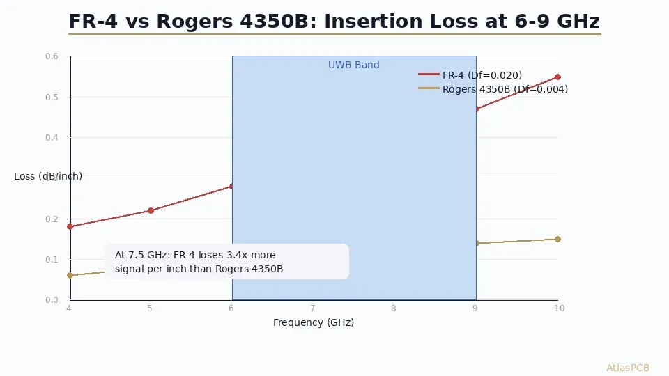
The second and more critical issue is insertion loss accumulation. At 7.5 GHz, standard FR-4 exhibits approximately 0.35-0.40 dB/inch of conductor-plus-dielectric loss on a 50-ohm microstrip. A typical UWB radar module with a patch antenna feed network might have 30-50mm of total RF trace length, accumulating 0.5-0.8 dB of loss before the signal even reaches the antenna. For a system with a 10 dB total link budget margin, losing nearly 1 dB in the PCB alone is significant — especially when Rogers 4350B would contribute only 0.15-0.25 dB for the same trace routing.
In our facility, we have processed over 200 UWB radar module designs in the past 18 months. The clear trend we observe: consumer-grade indoor ranging modules (Apple U1-type applications) can sometimes get away with modified FR-4 variants due to very short trace lengths (under 8mm total RF path), but any automotive, industrial, or outdoor UWB radar application with link distances beyond 20 meters requires Rogers on the antenna layer for reliable performance.
RF MATERIAL EXPERTISE
Need Help Choosing Materials for Your UWB Design?
Our RF engineers review your frequency plan and recommend optimal material/stackup combinations — Rogers, hybrid, or high-frequency FR-4 variants.
Get Material Recommendation >
Insertion Loss Budget: Quantifying the FR-4 Penalty
To make an informed material decision, you need actual loss numbers at your operating frequency — not datasheet values at 1 MHz. Here is what we measure on production panels using stripline resonator test methods:
| Frequency | FR-4 (IT-180A) | Megtron 4 | Rogers 4350B | Rogers 4003C |
|---|---|---|---|---|
| 5.0 GHz | 0.22 dB/in | 0.14 dB/in | 0.08 dB/in | 0.07 dB/in |
| 6.5 GHz | 0.30 dB/in | 0.18 dB/in | 0.10 dB/in | 0.08 dB/in |
| 7.5 GHz | 0.37 dB/in | 0.22 dB/in | 0.12 dB/in | 0.10 dB/in |
| 9.0 GHz | 0.47 dB/in | 0.28 dB/in | 0.14 dB/in | 0.12 dB/in |
These numbers include both dielectric loss and conductor loss on 1oz copper, 50-ohm microstrip. The conductor loss component is roughly equal for all materials (approximately 0.04-0.06 dB/inch at 7.5 GHz depending on trace width and copper roughness). The dominant difference is purely dielectric loss — which is where Rogers materials provide their fundamental advantage.
For a practical UWB radar example: consider a 24 GHz-band UWB module (channel 9 at 8.0 GHz center) with a 2x2 patch antenna array. The corporate feed network from the Decawave DW3000 IC to the antenna elements might traverse 35mm of total trace length (approximately 1.4 inches). On FR-4, this feed network alone introduces 0.52 dB of loss. On Rogers 4350B, the same geometry loses only 0.17 dB — a 0.35 dB improvement that directly translates to approximately 2 meters of additional ranging distance in a line-of-sight scenario.
Where FR-4 remains acceptable: if your total RF path from IC to antenna is under 8mm (0.3 inches), the absolute loss difference between FR-4 and Rogers drops below 0.1 dB. Some chip-antenna UWB designs achieve this with careful component placement. In these cases, the cost savings of FR-4 may be justified for high-volume consumer products where every cent matters.
Impedance Control: Batch-to-Batch Repeatability
Beyond raw insertion loss, the more insidious problem with FR-4 at UWB frequencies is impedance inconsistency between production batches. Standard FR-4 specifications allow Dk variation of +/-0.3 around a nominal value. At 6.5 GHz, a Dk shift from 4.2 to 4.5 changes your 50-ohm microstrip impedance to approximately 47 ohms — a 6% deviation that would fail most impedance-controlled PCB specifications.
Rogers 4350B specifies Dk at 3.48 +/-0.05, which translates to less than +/-1.5% impedance variation from material alone. When combined with our etching tolerance of +/-0.5 mil on trace width, total impedance variation stays within +/-3% measured — well inside the +/-5% specification that most UWB chipset vendors require.
Our process engineers track impedance yield data across all high-frequency PCB production. For UWB modules fabricated on Rogers 4350B over the past 12 months, impedance first-pass yield runs at 97.8%. The same designs attempted on standard FR-4 (before customers switched materials) showed 82-86% first-pass yield — meaning 14-18% of boards required either rework or rejection due to impedance exceedances.
IMPEDANCE CONTROLLED PCB
+/-5% Impedance on Rogers — 100% TDR Verified
Every impedance-controlled board ships with TDR test data. Our process achieves +/-3% typical on Rogers 4350B at frequencies through 10 GHz.
View RF PCB Capabilities >Recommended Stackup for UWB 6.5 GHz Radar Module
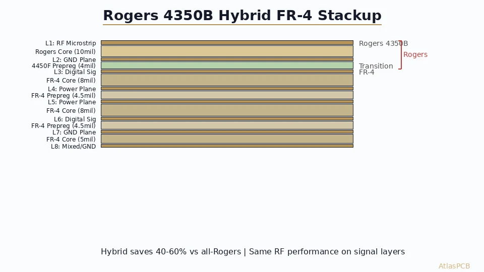
Based on our production experience with UWB radar modules for automotive (NXP SR150/SR040) and industrial positioning (Qorvo DW3720) applications, here is the stackup configuration we most frequently recommend:
4-Layer Hybrid (most common for compact modules):
| Layer | Material | Thickness | Function |
|---|---|---|---|
| L1 | Rogers 4350B | 0.254mm (10mil) | UWB antenna + RF feed |
| Prepreg | RO4450F | 0.100mm | Rogers-compatible bonding |
| L2 | Copper 1oz | 35um | Full ground reference |
| Core | FR-4 (Tg170) | 0.400mm | Digital/power core |
| L3 | Copper 1oz | 35um | Power plane |
| Prepreg | FR-4 2116 | 0.120mm | Standard prepreg |
| L4 | Copper 1oz | 35um | Digital signal + baseband |
Total thickness: approximately 1.1mm — suitable for module integration into sensor housings.
The critical detail most designers miss: the prepreg between L1 (Rogers) and L2 (ground) must be RO4450F or equivalent Rogers-compatible bondply, not standard FR-4 prepreg. Using FR-4 prepreg against a Rogers core creates a CTE mismatch at the lamination interface that can delaminate during thermal cycling. We have seen this failure mode on automotive modules that pass initial testing but fail after 500 thermal cycles (-40C to +125C).
For the L2-to-L4 section, standard FR-4 materials are perfectly appropriate. The baseband digital signals (SPI, I2C, UART to the host processor) operate well below 1 GHz and have no material sensitivity. This hybrid approach typically saves 55-65% compared to an all-Rogers construction while maintaining full RF performance on the critical antenna layer.
Design Guidelines: Getting UWB Trace Routing Right
The physical layout of RF traces at 6-9 GHz requires tighter discipline than lower-frequency designs. Based on failures we commonly catch during DFM review, here are the critical routing rules for UWB on Rogers:
Trace geometry for 50-ohm microstrip on 0.254mm Rogers 4350B (Dk=3.48):
- Trace width: 0.55mm (21.7 mil) for 50 ohms on 10mil Rogers over ground
- Trace width tolerance: +/-0.025mm (1 mil) for +/-5% impedance
- Minimum trace spacing: 3x trace width (1.65mm) to avoid coupling
- Via-to-trace clearance on L1: minimum 0.3mm from via pad edge to trace edge
Ground via fencing for microstrip:
- Via spacing along RF traces: 1.5mm maximum (lambda/4 at 9 GHz)
- Via diameter: 0.3mm drill, 0.6mm pad
- Purpose: contains the microstrip field and prevents substrate modes
Antenna feed network:
- All RF traces must be on L1 (Rogers surface) — no via transitions in the RF path
- Corporate feed networks for patch arrays should use Wilkinson dividers, not T-junctions
- Chamfer all 90-degree bends to 45 degrees or use curved traces (radius > 3x trace width)
One pattern we see repeatedly in failed designs: engineers route the RF feed network on L1 but place a decoupling capacitor’s ground return via directly under the feed line on L2, creating an impedance discontinuity. The fix is simple — keep a via exclusion zone of at least 1.0mm on either side of any RF trace, including on adjacent layers.
CHINA RF PCB MANUFACTURER
UWB Radar PCBs: Rogers 4350B with +/-5% Impedance
We stock Rogers 4350B in 0.254mm and 0.508mm. Typical lead time 8-12 days for 4-6 layer hybrid UWB modules. Upload your Gerber for instant DFM feedback.
Cost Optimization: When Hybrid Makes Sense
The material cost decision for UWB radar ultimately comes down to your production volume and link budget requirements:
| Volume | Recommendation | Rationale |
|---|---|---|
| Prototype (1-20 pcs) | All Rogers 4350B | Marginal absolute cost; eliminates material as a debug variable |
| Low volume (20-500 pcs) | Hybrid (Rogers L1 + FR-4 core) | Best balance of performance and cost |
| High volume (500+ pcs) | Hybrid optimized | Negotiate Rogers pricing; consider Isola Astra MT77 as alternative |
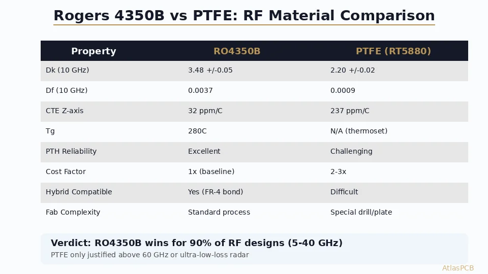
| Ultra-high volume (10k+) | Evaluate PTFE alternatives | Longer lead time but potentially lower per-unit at scale |
The hybrid stackup we recommend (Rogers L1 only) represents the sweet spot for most UWB radar applications. At our current pricing for a 4-layer hybrid 50x50mm board at quantity 100, the typical cost breaks down to approximately $28-38 per board — roughly 2.5-3x the price of equivalent all-FR-4, but with RF performance matching full-Rogers construction on the critical antenna layer.
One cost trap to avoid: some manufacturers quote hybrid boards but use generic FR-4 prepreg between the Rogers and FR-4 layers. This saves them $2-3 per panel but creates long-term reliability risks due to CTE mismatch. Always confirm that your fabricator uses Rogers-compatible bondply (RO4450F or equivalent) for the hybrid interface. We include this automatically in all hybrid RF builds — it is not an optional add-on.
ATLASPCB
Ready to Build Your UWB Radar Module?
Upload your design files for instant pricing on Rogers 4350B hybrid stackups. Our RF team reviews every UWB design for impedance, via fencing, and material compatibility.
Get Instant Quote >
Reviewed by AtlasPCB Engineering Team — 15+ years in advanced PCB fabrication for RF, HDI, and rigid-flex applications.
Related Reading:
About AtlasPCB — We specialize in complex PCB manufacturing for HDI, RF, and high-reliability applications. Explore our RF and high-frequency PCB services, Rogers RO4350B PCB manufacturing, or get an impedance-controlled PCB manufacturing . Every order includes free engineering review. Get your quote.
Reviewed by AtlasPCB Engineering Team — IPC-certified manufacturing specialists with 15+ years of production experience in HDI, RF, and high-reliability PCB fabrication. Content based on factory floor data and real customer design reviews.
Frequently Asked Questions
Can standard FR-4 work for UWB radar at 6.5 GHz?
What is the best Rogers material for 6-9 GHz UWB applications?
How much does a Rogers UWB radar PCB cost compared to FR-4?
What stackup do you recommend for a UWB 6.5 GHz radar module?
What impedance tolerance can you achieve on Rogers 4350B at 6-9 GHz?
- FR-4 vs Rogers PCB
- UWB radar PCB
- Rogers 4350B stackup
- impedance controlled PCB manufacturer
- RF PCB design