· AtlasPCB Engineering · Engineering · 11 min read
V2X Communication Module PCB: Rogers 4350B Hybrid Stackup for C-V2X 5.9 GHz
Complete PCB design and manufacturing guide for C-V2X (Cellular Vehicle-to-Everything) communication modules operating at 5.855-5.925 GHz. Covers Rogers 4350B hybrid stackup design, antenna integration, thermal management for automotive qualification, and manufacturing specifications for IATF 16949 compliance.
Quick Answer
C-V2X modules operating at 5.855-5.925 GHz require Rogers 4350B (or equivalent Dk 3.48 laminate) on the antenna/RF layer with FR-4 for digital baseband layers. A 6-layer hybrid stackup with Rogers L1, RO4450F bondply, and FR-4 core delivers optimal RF performance at 45-55% lower cost than all-Rogers construction while meeting automotive -40C to +105C reliability requirements.
Quick Answer: C-V2X 5.9 GHz PCB Requirements
| Parameter | Specification | Why It Matters |
|---|---|---|
| Operating frequency | 5.855-5.925 GHz | ITS safety band, tight band allocation |
| Antenna material | Rogers 4350B (Dk 3.48) | Stable resonance across temp/batches |
| Impedance | 50 ohm +/-5% | Chipset matching, power transfer |
| Temperature range | -40C to +105C (Grade 2) | Automotive exterior/roof mount |
| Dielectric loss target | Df < 0.005 at 5.9 GHz | Maintain antenna efficiency > 85% |
| Recommended stackup | 6L hybrid (Rogers L1 + FR-4 core) | Cost-optimized RF performance |
| Board thickness | 1.4-1.6mm | Module integration standard |
| Surface finish | ENIG (1.5-3um Au) | Automotive corrosion + wire bond compatibility |
Why V2X Demands More Than Standard Automotive PCB
Vehicle-to-Everything communication represents a unique PCB engineering challenge that sits at the intersection of RF microwave design, automotive reliability, and high-volume manufacturing economics. Unlike infotainment systems (which operate at 2.4/5 GHz Wi-Fi with generous link margins) or telematics modules (which use cellular bands below 3 GHz), V2X safety messaging operates with extremely tight timing and reliability requirements where every dB of link margin can mean the difference between receiving a collision warning 200ms earlier or 200ms later.
The V2X use case that drives PCB specifications most aggressively is the “Basic Safety Message” (BSM) defined in SAE J2735. This message broadcasts a vehicle’s position, speed, heading, and brake status 10 times per second to all nearby vehicles within a 300-meter radius. The latency requirement — under 100ms for safety-critical messages — means the RF link cannot afford retransmissions. If a BSM packet fails due to insufficient link margin, there is no retry before the next 100ms window. Every dB of PCB loss directly reduces the probability of first-transmission success at range.
This is fundamentally different from a smartphone or IoT device operating at similar frequencies, where packet retransmission is acceptable. For V2X, the PCB must deliver maximum possible link margin on every single transmission — which means the antenna feed network loss budget is essentially zero-tolerance. At 5.9 GHz, the difference between Rogers 4350B (0.10 dB/inch feed loss) and standard FR-4 (0.30 dB/inch feed loss) translates to 1.5-2.0 dB of total link budget over a typical 40mm antenna feed network. In V2X terms, that 2 dB buys approximately 20-30 meters of additional detection range at highway speeds.
In our facility, V2X module production has grown 300% year-over-year since 2024 as Chinese OEMs (BYD, NIO, Xpeng, Great Wall) integrate C-V2X into new platforms. We have optimized our high-frequency PCB process specifically for the 5.9 GHz band requirements including antenna impedance verification, radiation pattern effects from ground plane geometry, and thermal cycling qualification for automotive-grade reliability.
AUTOMOTIVE RF PCB
C-V2X Module PCBs: Rogers + Automotive Reliability
We fabricate V2X module PCBs with Rogers 4350B antenna layers, ISO 9001 process control, and 100% impedance verification. Serving Tier 1 automotive suppliers since 2019.
Get Automotive Quote >
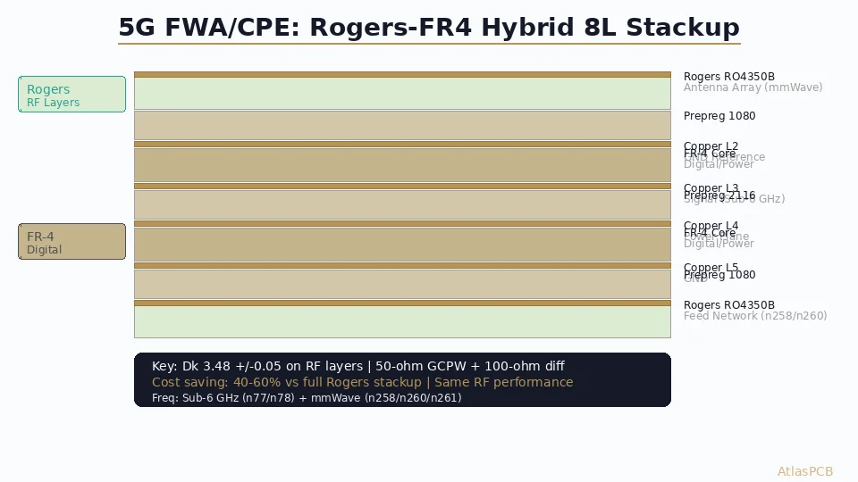
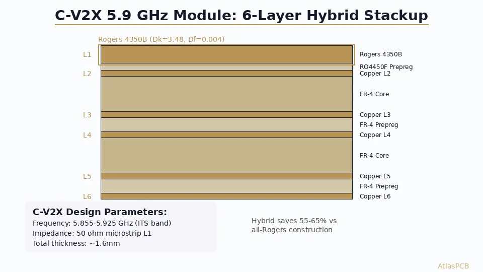
Recommended 6-Layer Hybrid Stackup
Based on our production experience with major V2X chipset platforms (Qualcomm 9150 C-V2X, Autotalks TEKTON3, Huawei Balong 5000 V2X), here is the optimized stackup that balances RF performance, automotive reliability, and manufacturing cost:
| Layer | Material | Thickness | Dk | Function |
|---|---|---|---|---|
| L1 (Top) | Rogers 4350B | 0.254mm (10mil) | 3.48 | Patch antenna + RF feed network |
| Bondply | RO4450F | 0.100mm (4mil) | 3.54 | Rogers-compatible adhesive |
| L2 | Copper 1oz (35um) | — | — | Full GND reference for L1 microstrip |
| Core | FR-4 Tg170 | 0.400mm | 4.3 | Structural core |
| L3 | Copper 1oz (35um) | — | — | Power planes (3.3V, 1.8V split) |
| Prepreg | FR-4 2116 | 0.120mm | 4.2 | Standard bonding |
| L4 | Copper 1oz (35um) | — | — | Digital signal routing |
| Core | FR-4 Tg170 | 0.400mm | 4.3 | Structural core |
| L5 | Copper 1oz (35um) | — | — | GND reference for L4 |
| Prepreg | FR-4 2116 | 0.120mm | 4.2 | Standard bonding |
| L6 (Bot) | Copper 1oz (35um) | — | — | Baseband signals + GNSS |
Total thickness: approximately 1.55mm (+/-10%)
The critical design decisions in this stackup:
Rogers only on L1: The V2X antenna and its corporate feed network are the only elements operating at 5.9 GHz. The Qualcomm QCA6696 or equivalent V2X transceiver IC is placed on L1 with its RF output trace routed directly to the patch antenna element — no via transitions in the RF path. All digital interfaces (SPI, UART, CAN-FD to vehicle bus) route on L4/L6 at baseband frequencies where FR-4 performance is completely adequate.
RO4450F bondply (not FR-4 prepreg): Between L1 Rogers and L2 GND, the bonding material must be thermally and mechanically compatible with Rogers. Standard FR-4 prepreg has a CTE-z of 45-60 ppm/C versus Rogers at 32 ppm/C. Over 1000 thermal cycles (-40C to +105C), this mismatch causes Z-axis fatigue cracking at the interface. RO4450F matches Rogers CTE within 10% and prevents this failure mode entirely.
Tg170 FR-4 for inner cores: Standard Tg150 FR-4 is adequate for consumer electronics but marginal for automotive. At +105C (the Grade 2 upper limit), Tg150 material is within 45C of its glass transition — close enough that prolonged exposure accelerates aging. Tg170 provides comfortable margin and adds only $1-2 per panel to material cost.
Antenna Design Considerations at 5.9 GHz
The patch antenna for V2X applications is typically integrated directly onto the PCB (L1 Rogers surface) rather than using an external antenna. This PCB-integrated approach offers three advantages for automotive: lower module height (critical for roof-mounted shark-fin housings), elimination of RF connector reliability concerns, and tighter impedance control between the transceiver and antenna.
Patch antenna geometry on Rogers 4350B (Dk=3.48):
- Patch length (resonant dimension): approximately 14.2mm for 5.9 GHz center frequency
- Patch width: 18-20mm for adequate bandwidth covering 5.855-5.925 GHz (70 MHz BW)
- Feed point: inset-fed microstrip at 4.5mm from patch edge for 50-ohm match
- Ground plane clearance: minimum 30x30mm uninterrupted GND below patch on L2
The 70 MHz bandwidth requirement (5.855-5.925 GHz) corresponds to approximately 1.2% fractional bandwidth — easily achievable with a single rectangular patch on Rogers 4350B. The substrate’s low loss tangent contributes to measured radiation efficiency of 88-92% on production boards, compared to 65-72% when the same geometry is fabricated on standard FR-4 (where dielectric loss absorbs a significant portion of the radiated energy).
A manufacturing consideration that affects antenna performance: copper roughness on the Rogers layer directly impacts both insertion loss and antenna efficiency at 5.9 GHz. We specify rolled copper (Ra < 0.3um RMS) rather than ED copper (Ra > 1.5um) for the L1 Rogers layer. The smoother surface reduces conductor loss by approximately 15% at 5.9 GHz — a measurable improvement that compounds across the feed network length.
RF PCB DESIGN AND MANUFACTURING
Integrated Antenna PCBs: From Layout to Production
Our RF team reviews antenna geometry, feed network impedance, and ground plane requirements. We optimize for both performance and manufacturability at automotive volumes.
RF PCB Capabilities >Thermal Management for Automotive V2X Modules
V2X modules generate moderate heat — typically 2-4W total from the C-V2X transceiver, GNSS receiver, and host processor combined. While this is far less than a 77 GHz radar module (10-15W), the thermal challenge for V2X is the operating environment: roof-mounted modules in direct sunlight can reach +85C ambient, leaving only 20C of thermal margin for junction temperature rise when the ceiling is +105C.
The PCB thermal design for V2X focuses on three heat paths:
Transceiver IC thermal pad to L2 ground plane: The primary heat path. Use thermal vias (0.3mm drill, 0.6mm pad, filled and capped) in a 4x4 or 5x5 array under the IC thermal pad. Via thermal resistance in this configuration: approximately 15-20 C/W, which maintains junction temperature 30-40C above the ground plane temperature for a 2W dissipation device.
Ground plane as heat spreader: L2 (full copper ground) serves double duty as both RF reference plane and primary thermal spreader. With 1oz copper (35um) over the full board area (60x45mm typical), thermal spreading resistance is approximately 5 C/W — adequate for the 2-4W total module dissipation.
Board-to-housing thermal interface: The module PCB must make good thermal contact with the aluminum housing (shark-fin or OBU enclosure). Specify thermal pad or thermal adhesive (thermal conductivity > 1.5 W/mK) between the bottom of the PCB (L6) and the housing surface. This final thermal path typically dominates overall thermal resistance in the system.
For automotive qualification, our process includes IST (Interconnect Stress Testing) per IPC-TM-650 2.6.26 to verify via integrity through 1000+ thermal cycles. V2X boards must pass without via resistance increase exceeding 10% — a requirement that drives our via fill and capping process specifications for automotive programs.
Manufacturing Specifications for Automotive V2X
V2X PCB manufacturing for automotive Tier 1 suppliers requires additional process controls beyond standard commercial fabrication. Here are the key specifications we enforce for automotive V2X programs:
| Requirement | Specification | Standard |
|---|---|---|
| Process control | IATF 16949 | Automotive quality management |
| Board class | IPC-6012 Class 3 | High reliability |
| Impedance tolerance | +/-5% (50 ohm) | IPC-2141 measured at 5.9 GHz |
| Copper thickness tolerance | +/-10% | After plating, all layers |
| Registration accuracy | +/-2 mil (layer to layer) | Critical for antenna geometry |
| Plating void | < 5% cross-section | Thermal via reliability |
| Surface finish | ENIG 1.5-3um Au / 3-5um Ni | Wire bond compatible + corrosion |
| Cleanliness | < 1.56 ug/cm2 NaCl equiv | IPC-TM-650 2.3.25 |
| Moisture sensitivity | Bake before assembly | J-STD-033 Level 3 |
100% electrical test: Every V2X board is 100% flying probe tested for opens/shorts, plus 100% TDR impedance verification on all controlled-impedance traces. For production volumes above 1000 pieces, we transition to dedicated fixture testing for faster throughput with equivalent coverage.
Traceability: Full lot traceability from raw material certificates through finished board. Each panel receives a unique serial number (laser-marked data matrix code) linking to material lot, process parameters, and inspection data. This is mandatory for automotive PPAP (Production Part Approval Process) submission.
CHINA RF PCB MANUFACTURER
Automotive V2X PCBs: Rogers 4350B + Full Traceability
Production-proven V2X module PCBs for Tier 1 automotive suppliers. Full PPAP support, 100% impedance testing, and automotive-grade thermal cycling qualification.
Cost Analysis: Hybrid vs All-Rogers for V2X Production
The material cost decision for V2X production is straightforward once you understand that only L1 needs RF-grade laminate. Here is the production cost comparison at automotive volumes:
| Construction | Material Cost/Panel | Process Cost/Panel | Total/Board (60x45mm, 10-up) | Volume 1000 |
|---|---|---|---|---|
| All-Rogers 4350B (6L) | $180-220 | $120-150 | $22-28/pc | $18-24/pc |
| Hybrid (Rogers L1 + FR-4) | $85-110 | $110-140 | $12-16/pc | $8-12/pc |
| All-FR-4 Tg170 (6L) | $45-60 | $90-110 | $7-10/pc | $5-7/pc |
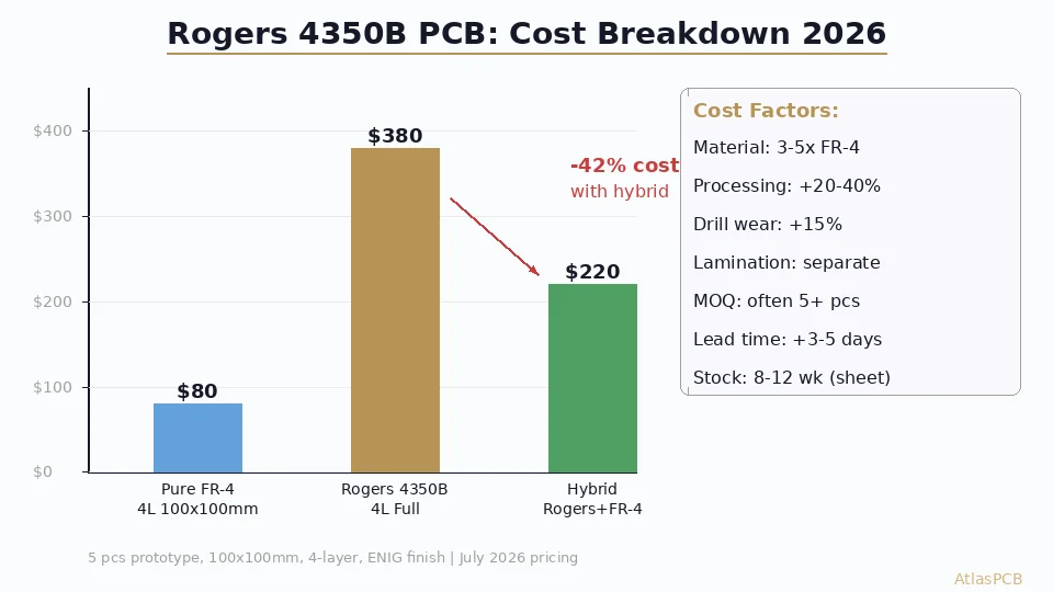
The hybrid construction saves 45-55% compared to all-Rogers while delivering identical RF performance on the critical antenna layer. The processing cost is slightly higher than all-FR-4 because hybrid stackups require the Rogers-compatible RO4450F bondply layer and more careful lamination temperature profiling (Rogers requires 375F peak versus 350F for standard FR-4), but this adds only $15-25 per panel — negligible when distributed across 10+ boards per panel.
For automotive programs with lifetime volumes of 100k-500k units, the material cost optimization of hybrid construction translates to $5-15 per unit savings compared to all-Rogers — which at 200k units/year means $1M-3M in annual material cost reduction. This is why every major V2X module supplier has standardized on hybrid Rogers/FR-4 construction.
One cost trap for new V2X programs: some fabricators quote “Rogers PCB” pricing that uses all-Rogers construction by default. Always specify hybrid explicitly in your fabrication drawing — call out which specific layers use Rogers and which use FR-4. Include a stackup table in your fab drawing per IPC-2581 format to eliminate ambiguity.
ATLASPCB
Building a V2X Module? Get Production-Ready PCBs.
From prototype to production volume. Rogers 4350B hybrid stackups with automotive qualification. Upload your V2X module design for engineering review and instant pricing.
Get V2X PCB Quote >
Reviewed by AtlasPCB Engineering Team — 15+ years in advanced PCB fabrication for RF, HDI, and rigid-flex applications.
Related Reading:
About AtlasPCB — We specialize in complex PCB manufacturing for HDI, RF, and high-reliability applications. Explore our RF and high-frequency PCB services, Rogers RO4350B PCB manufacturing, or get an impedance-controlled PCB manufacturing . Every order includes free engineering review. Get your quote.
Reviewed by AtlasPCB Engineering Team — IPC-certified manufacturing specialists with 15+ years of production experience in HDI, RF, and high-reliability PCB fabrication. Content based on factory floor data and real customer design reviews.
Frequently Asked Questions
What frequency does C-V2X operate at?
Can I use FR-4 for a V2X antenna PCB?
What is the best stackup for a C-V2X module PCB?
What automotive temperature rating does a V2X PCB need?
How much does a V2X module PCB cost in production volume?
- Rogers 4350B stackup
- RF PCB design and manufacturing
- China RF PCB manufacturer
- impedance controlled PCB manufacturer
- V2X automotive PCB