· Thomas Webb · Materials · 11 min read
Rogers RO4835 vs RO4350B: Selecting the Right Laminate for mmWave Applications
A fabrication-informed comparison of Rogers RO4835 and RO4350B laminates for millimeter-wave PCB design, covering dielectric properties, loss tangent behavior, thermal performance, processing differences, and selection criteria for 24-77 GHz applications.

The Rogers RO4000 series has become the default material family for millimeter-wave PCB applications, combining the thermoset processing characteristics that fabricators prefer with dielectric properties that approach PTFE-based materials in the frequency ranges that matter most. Within this family, the RO4350B and RO4835 represent two distinct formulations that designers often conflate or select based on incomplete information. Having processed thousands of panels in both materials across applications spanning automotive radar at 77 GHz, 5G infrastructure at 28 GHz, and satellite communications at 24 GHz Ka-band, we have developed detailed understanding of where each material excels, where each struggles, and how the differences in their behavior translate to measurable performance and manufacturability in real production.
Material Composition and Formulation Differences
Both RO4350B and RO4835 belong to Rogers Corporation’s hydrocarbon ceramic family, using woven glass reinforcement with thermoset resin systems filled with ceramic particles to control dielectric constant. The critical distinction lies in their resin formulations and the resulting high-frequency performance characteristics. RO4350B uses Rogers’ original ceramic-filled hydrocarbon resin system, providing a dielectric constant of 3.48 at 10 GHz (process specification) with a dissipation factor (loss tangent) of 0.0037 at the same frequency. RO4835 represents a refinement of this formulation specifically targeting improved high-frequency loss performance, achieving a dissipation factor of 0.0032 at 10 GHz while maintaining a very similar dielectric constant of 3.48.
That 0.0005 difference in loss tangent may appear trivial on a datasheet, but its significance grows with frequency and propagation length. At 77 GHz, the loss tangent difference translates to approximately 0.1 to 0.15 dB per centimeter additional insertion loss for RO4350B compared to RO4835 on typical microstrip geometries. For an automotive radar antenna feed network with 5 centimeters of total propagation path, this equates to 0.5 to 0.75 dB of additional loss — enough to measurably impact radar detection range and signal-to-noise ratio in the receive path.
The glass weave style also differs between the two materials in their standard offerings. RO4835 is typically available with 1080 glass fabric, which uses a finer weave pattern that reduces the “glass weave effect” — periodic variations in dielectric constant that create unwanted phase distortion for signals propagating at certain angles relative to the weave. RO4350B is available in multiple glass styles including 1080 and the coarser 1674 fabric, giving designers more thickness options but potentially introducing greater dielectric constant variation in applications sensitive to weave periodicity.
Measured Performance at Millimeter-Wave Frequencies
Published datasheet values are measured at 10 GHz per IPC TM-650 test methods, but real millimeter-wave applications operate at frequencies three to eight times higher. Dielectric properties are frequency-dependent, and the behavior of each material at the actual operating frequency matters more than catalog values. Based on our in-house split-post resonator testing and customer-reported vector network analyzer characterization data, we observe the following trends.
At 28 GHz, RO4350B exhibits an effective dielectric constant of approximately 3.52 to 3.55 (slightly elevated from the 10 GHz value due to the frequency dispersion characteristics of the ceramic filler system) with loss tangent increasing to approximately 0.0042 to 0.0048. RO4835 at the same frequency shows effective dielectric constant of 3.50 to 3.53 with loss tangent of 0.0035 to 0.0040. The relative advantage of RO4835 becomes more pronounced as frequency increases.
At 77 GHz, the separation widens further. RO4350B loss tangent rises to approximately 0.0055 to 0.0065 in our measurements, while RO4835 maintains values between 0.0040 and 0.0050. This 25 to 30 percent reduction in dielectric loss at 77 GHz makes RO4835 the clearly superior choice for automotive radar applications where every tenth of a dB in the antenna and feed network directly impacts detection range. The difference is particularly important for long-range radar modules operating at ranges beyond 200 meters, where cumulative path loss budgets are tight.
However, it is worth noting that the absolute performance of either Rogers material at 77 GHz still falls short of pure PTFE materials like Rogers RT/duroid 5880 (loss tangent approximately 0.0009 at 10 GHz). The RO4000 family’s advantage is not achieving the lowest possible loss but rather providing acceptable loss performance within a fabrication process that closely resembles standard FR-4 processing — a distinction that dramatically impacts cost, lead time, and fabricator availability.
Fabrication Processing Comparison
From a PCB manufacturer’s perspective, both RO4350B and RO4835 process similarly because they share the same thermoset resin family. Unlike PTFE materials that require sodium etching or plasma treatment for adhesion promotion, both RO4000 materials accept standard copper bonding treatments and multilayer lamination processes. The materials can be drilled with standard carbide tooling, develop clean hole walls without excessive smear, and plate reliably using conventional desmear and electroless copper processes.
The subtle processing differences we observe relate primarily to lamination behavior in hybrid stackups where Rogers material layers combine with standard FR-4 or prepreg layers. RO4835’s slightly different resin flow characteristics during lamination require adjusted pressure profiles compared to RO4350B when bonding with Rogers 4450F bondply. Our process engineers have documented that RO4835 panels exhibit approximately 5 to 8 percent less resin flow during lamination at equivalent pressures, requiring slightly higher temperature or extended press time to achieve void-free bonding at interfaces. This does not present a significant manufacturing challenge but does mean that lamination recipes validated for RO4350B hybrid stackups cannot be directly transferred to RO4835 without verification.
Both materials machine well during routing and scoring operations. Neither material exhibits the delamination tendency that pure PTFE materials show during mechanical finishing operations. Edge quality after routing is clean with minimal glass fiber pullout, which matters for board outlines that form part of RF ground structures or waveguide sidewalls.
Moisture absorption differs marginally between the two materials — RO4835 absorbs approximately 0.06 percent moisture at room temperature per Rogers specifications, compared to 0.06 percent for RO4350B. In practice, both materials are sufficiently hygroscopic stability that moisture-related detuning is negligible for most applications when boards are properly handled and stored in controlled environments before assembly.
Thermal Performance and Power Handling
Both materials share identical glass transition temperature specifications above 280 degrees Celsius, providing comfortable margin above lead-free reflow temperatures. Their thermal conductivity values are comparable at approximately 0.62 W/mK for RO4350B and 0.66 W/mK for RO4835, making neither material a thermal bottleneck in typical RF applications. However, for high-power amplifier circuits where substrate thermal resistance directly impacts device junction temperature, the small thermal conductivity advantage of RO4835 provides marginally better heat spreading.
Where thermal performance becomes practically significant is in the coefficient of thermal expansion behavior. Both materials exhibit CTE values of approximately 14 ppm per degree Celsius in the X-Y plane and 46 ppm per degree Celsius in the Z-axis. This Z-axis CTE is lower than standard FR-4 (typically 50 to 70 ppm/C above Tg), providing better reliability for plated through-hole vias in thick multilayer constructions. The matched X-Y CTE values between the two materials mean they can be combined in hybrid stackups without introducing CTE mismatch stresses between layers — an important consideration for high-layer-count designs using different Rogers materials on different signal layers.
For power amplifier applications, the substrate dielectric loss directly converts to heat generation within the laminate itself. At 28 GHz with 2 watts of RF power propagating through a 50-ohm microstrip on 0.254 millimeter thick material, the dielectric heating in RO4350B generates approximately 18 milliwatts per centimeter of line length compared to 15 milliwatts per centimeter for RO4835. While these numbers are small individually, they contribute to the total thermal budget in dense circuits with many parallel feed lines, and reducing internal heat generation by 15 to 20 percent simplifies thermal management in module-level designs.
Cost and Availability Considerations
Material cost represents a significant portion of total fabrication cost for high-frequency boards, and the pricing difference between RO4835 and RO4350B reflects their positioning in the Rogers product portfolio. RO4350B, as the higher-volume, longer-established product, benefits from economies of scale in production and broader distributor stocking. Standard thicknesses (0.254 mm, 0.508 mm, 0.762 mm) in 1-ounce copper are typically available from stock with lead times of two to four weeks. RO4835 commands a 10 to 20 percent price premium over RO4350B in equivalent thicknesses and copper weights, with slightly longer procurement lead times of three to six weeks for standard configurations.
Panel sizes follow Rogers’ standard offerings for both materials, with 12 by 18 inch and 18 by 24 inch panels being the most common. Non-standard thicknesses or copper weights in RO4835 may require minimum order quantities or extended lead times because fabrication runs are less frequent than for the higher-volume RO4350B.
From our procurement experience managing material inventory for both products, RO4350B availability has remained stable through the supply chain disruptions of recent years because its production volume justifies dedicated manufacturing schedules at Rogers’ facilities. RO4835, while not scarce, occasionally experiences allocation constraints during high-demand periods for automotive radar substrates, as the 77 GHz autonomous driving market consumes an increasing share of total RO4835 production capacity.
Hybrid Stackup Design Strategies
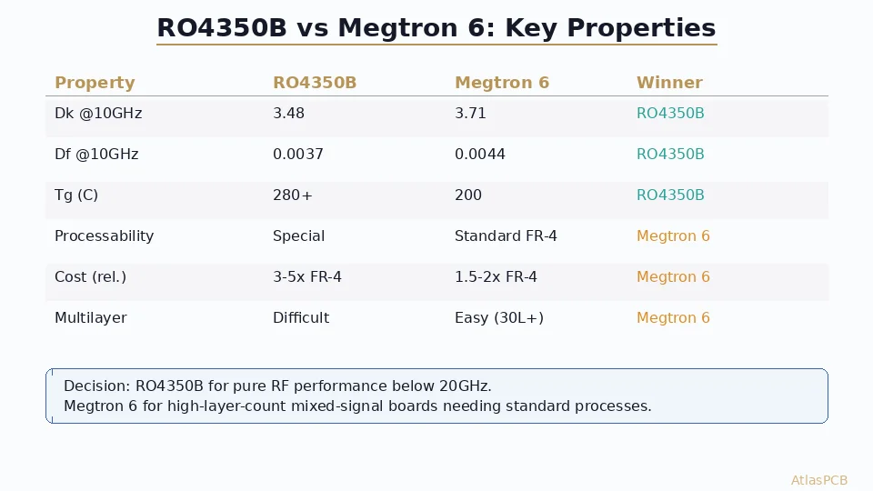
Most practical millimeter-wave designs do not use Rogers material for all layers. Cost optimization and mechanical requirements dictate hybrid stackups where Rogers material appears only on the signal-carrying layers that demand low-loss performance, while standard FR-4 or mid-loss materials (Panasonic Megtron-6, Isola I-Tera MT40) handle power distribution and non-critical signal layers. Both RO4835 and RO4350B integrate well into hybrid constructions, though designers must account for the dielectric constant mismatch at layer transitions.
A common 8-layer hybrid stackup for 77 GHz automotive radar places RO4835 as the top two layers (antenna and feed network), with Megtron-6 handling the inner digital control layers and a standard FR-4 core providing mechanical rigidity. The lamination sequence bonds Rogers layers to the core using Rogers 4450F or 4450B bondply, which is specifically formulated for this interface. Our standard process validates each new hybrid stackup combination through thermal shock testing and cross-sectional analysis before releasing to production, ensuring void-free bonding at all material interfaces.
When designing such stackups, the impedance calculation for microstrip and stripline structures must use the actual measured dielectric constant at the operating frequency rather than the published 10 GHz value. Additionally, the bondply thickness (which acts as a dielectric spacer between the Rogers signal layer and adjacent ground layer) must be carefully controlled because its dielectric constant differs from the Rogers laminate itself. Designers sometimes overlook this, specifying impedance calculations based solely on the laminate Dk while ignoring the bondply Dk, resulting in systematic impedance errors of 3 to 5 ohms that require post-fabrication compensation.
Selection Criteria and Recommendations
The decision between RO4835 and RO4350B should be driven by the operating frequency and the loss budget of the specific application. For applications below 24 GHz — including WiFi 6E/7 front-end modules, sub-6 GHz 5G infrastructure, and general microwave circuits — RO4350B provides fully adequate loss performance at lower cost and with better material availability. The additional loss tangent penalty at these frequencies is small enough that it rarely impacts system-level performance margins.
For applications operating between 24 and 40 GHz, including 5G millimeter-wave base station antenna arrays and Ka-band satellite terminals, the choice depends on the length of RF propagation paths and the tightness of the loss budget. Short-path designs (less than 3 centimeters total propagation) can use RO4350B without measurable performance penalty. Longer-path designs, particularly large antenna arrays with corporate feed networks spanning 5 centimeters or more, benefit meaningfully from RO4835’s lower loss tangent.
For applications at 60 GHz and above, including 77 GHz automotive radar and WiGig modules, RO4835 should be the default selection whenever budget and availability permit. The loss tangent advantage at these frequencies is substantial enough to directly impact system performance metrics like detection range, data throughput, and power efficiency. The 10 to 20 percent material cost premium is typically insignificant relative to the total module cost and the value of the performance improvement.
Regardless of which material is selected, successful millimeter-wave fabrication requires close collaboration between the design team and the fabricator during the stackup definition phase. Material selection, layer registration requirements, surface finish compatibility (immersion silver is preferred over ENIG for RF surfaces), and impedance control tolerances all interact and must be optimized as a system rather than specified independently.
Reviewed by AtlasPCB Engineering Team
ATLASPCB RF MATERIALS
Rogers RO4835 and RO4350B In Stock
We maintain inventory of standard Rogers thicknesses for rapid-turn mmWave prototypes. Hybrid stackup design support included with every RF quotation.
Request RF Board Quote ›About AtlasPCB — We specialize in complex PCB manufacturing for HDI, RF, and high-reliability applications. Explore our RF and high-frequency PCB services, or get an Rogers RO4350B PCB manufacturing . Every order includes free engineering review. Get your quote.
Reviewed by AtlasPCB Engineering Team — IPC-certified manufacturing specialists with 15+ years of production experience in HDI, RF, and high-reliability PCB fabrication. Content based on factory floor data and real customer design reviews.
- Rogers
- RO4835
- RO4350B
- mmWave
- RF materials
- laminate selection
- high frequency PCB