· Engineering · 8 min read
Rigid-Flex PCB Manufacturer Selection: Capability Assessment, Qualification Criteria, and What Separates Production-Ready from Prototype-Only Suppliers
How to evaluate and select a rigid-flex PCB manufacturer based on layer count capability, bend radius specifications, material systems, yield data, and production scalability. Includes qualification checklists and red flags that indicate a supplier is stretching beyond proven capability.
Quick Answer
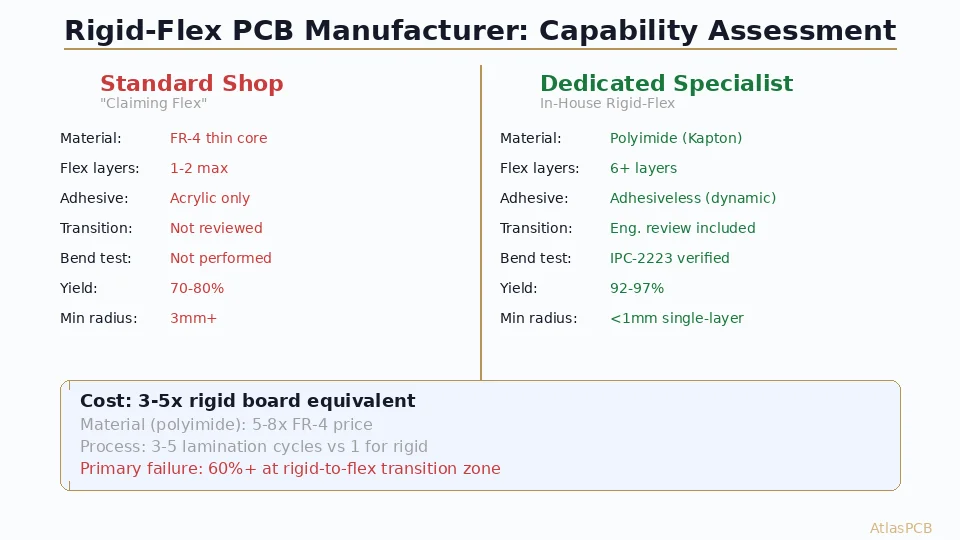
Selecting a rigid-flex PCB manufacturer requires evaluating layer count capability (not just maximum but proven production volume at that layer count), bend radius versus flex layer thickness, material system compatibility (adhesive-based versus adhesiveless polyimide construction), and demonstrated production yield data. A prototype-only supplier may achieve a complex rigid-flex design once at 60% yield; a production-qualified manufacturer achieves the same design consistently at 90%+ yield. Key differentiators include: in-house flex material processing (not subcontracted), proven dynamic flex capability with cycle-life test data, and IPC-2223 compliance with documented process controls.
Rigid-flex PCB manufacturing sits at the intersection of two distinct fabrication disciplines: traditional rigid PCB processing and flexible circuit manufacturing. The challenge is not simply combining them — it is maintaining the reliability standards of both while managing the mechanical and material compatibility issues that arise at every rigid-to-flex transition zone.
This guide addresses the manufacturer selection problem from the perspective of an engineering team evaluating potential rigid-flex suppliers. The criteria that matter, the questions to ask, and the red flags that indicate a supplier is marketing capability they cannot reliably deliver.
Why Manufacturer Selection Matters More for Rigid-Flex
For standard rigid PCBs, manufacturer capability is relatively uniform above a baseline quality level. A 6-layer FR-4 board with 4/4mil trace/space is within production capability of hundreds of fabricators worldwide. Pricing and lead time are the primary differentiators.
Rigid-flex is different. The process window is narrow, the material behavior is less forgiving, and the failure modes are subtle. A manufacturer who produces excellent rigid multilayer boards may struggle with rigid-flex because:
Material handling expertise is different. Polyimide flex materials are hygroscopic — they absorb moisture that causes delamination during lamination if not properly baked. They are dimensionally unstable compared to FR-4 and require different artwork compensation algorithms. They cannot tolerate the same chemical processes used for rigid board cleaning.
Registration challenges multiply. Flex materials stretch during lamination in ways that rigid FR-4 does not. Aligning rigid and flex layers to the same registration datum requires empirically-developed scaling factors specific to the material system, press cycle, and stackup. A fabricator without sufficient rigid-flex production history does not have this data.
Yield is dramatically lower. First-time rigid-flex yield for a new manufacturer is often 40-60% compared to 90%+ for experienced fabricators building the same design. The scrap occurs at multiple process steps — flex layer deformation during lamination, coverlay misregistration, controlled-depth routing damage to flex layers, delamination at rigid-flex transition zones.
Failure modes are not always visible. A rigid-flex board can pass electrical test and visual inspection while harboring latent reliability issues: micro-cracks at the rigid-flex transition, copper fatigue in insufficient-radius bend zones, or adhesive degradation from thermal processing. These failures manifest in the field, not in incoming inspection.
Critical Capability Assessment Criteria
Layer Count and Flex Zone Complexity
Do not evaluate a manufacturer solely on their maximum stated layer count. Instead, ask:
- What is your highest layer count rigid-flex in current production (not just prototype)?
- What is the maximum number of flex zones you have produced simultaneously in one design?
- What flex layer configurations have you produced? (single-sided flex, double-sided flex, multilayer flex sections)
A manufacturer comfortable with 4-layer rigid-flex (1 flex zone, single-sided) may be entirely unqualified for your 14-layer design with 3 double-sided flex zones. These are fundamentally different manufacturing challenges.
At AtlasPCB, we support rigid-flex from 2 through 22 layers with up to 4 independent flex zones. Our standard production includes both single-sided and double-sided flex configurations, with multilayer flex sections (flex layers within the flexible zone) available for high-density routing through bend areas.
Bend Radius Specifications
The achievable bend radius depends on flex section thickness, copper weight, and construction type (adhesive versus adhesiveless). A qualified rigid-flex manufacturer provides specific data:
Static bend applications (installed once, never moved):
- Minimum bend radius = 6 × flex section total thickness
- Example: 0.2mm flex section → 1.2mm minimum bend radius
- Copper elongation limit: 2-3% maximum at outer radius
Dynamic bend applications (repeated cycling):
- Minimum bend radius = 12-20 × flex section total thickness
- Example: 0.15mm flex section → 1.8-3.0mm minimum bend radius
- Requires rolled annealed (RA) copper, not electrodeposited (ED)
- Must pass cycle-life testing: 100,000+ cycles without failure
Ask your candidate manufacturer: “At what bend radius and cycle count do you guarantee reliability for my specific stackup?” If they cannot answer with specific numbers backed by test data, they are guessing.
Material Systems
Rigid-flex material selection involves three categories, each with significant implications:
Flex core material:
- Kapton (DuPont polyimide): industry standard, 25μm or 50μm thickness
- Adhesiveless polyimide: copper deposited directly on PI without adhesive layers
- LCP (Liquid Crystal Polymer): for applications requiring very low moisture absorption
Coverlay (flex protective layer):
- Polyimide coverlay with adhesive: standard, 12.5μm PI + 25μm adhesive typical
- Photo-imageable coverlay (PIFLEX): for fine-pitch component mounting on flex zones
- No coverlay (exposed flex copper with immersion finish): for certain connector interfaces
Bonding system (rigid-to-flex interface):
- Acrylic adhesive: lowest cost, but Tg limit around 100°C
- Epoxy adhesive: higher thermal performance (Tg 150-180°C)
- No-flow prepreg: highest reliability rigid-flex bonding for multilayer designs
- Thermoplastic adhesive: for high-layer-count constructions requiring multiple lamination cycles
A manufacturer’s material certification library indicates their production experience. Ask for their approved material list and verify it includes the specific flex system your design requires. If they need to “qualify a new material” for your project, add 4-6 weeks and budget for qualification builds.
Controlled-Depth Routing
The flex outline in a rigid-flex board is defined by controlled-depth routing — the router must cut through the rigid layers precisely to the rigid-flex interface without damaging the underlying flex layers. This process has tolerance requirements of ±50μm in Z-axis depth.
A router that plunges too deep damages the flex coverlay or copper. Too shallow leaves rigid material bridging the flex zone that prevents bending. Either failure scraps the board.
Qualified rigid-flex manufacturers use:
- Laser-measured depth feedback during routing
- Sacrificial backup layers (copper foil references) that the router stops upon contact
- Acoustic or electrical depth-detection systems
Ask your candidate manufacturer: “What Z-axis depth tolerance do you hold on flex outline routing?” Anything wider than ±75μm suggests immature capability.
Transition Zone Reliability
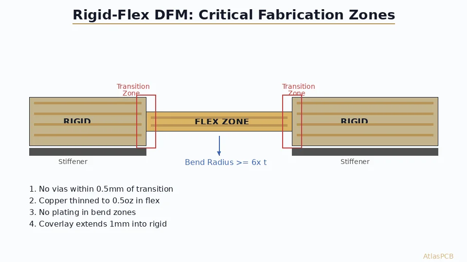
The rigid-to-flex transition zone is where most rigid-flex reliability issues originate. At this boundary, the stiff rigid laminate meets the flexible polyimide — creating a stress concentration point that experiences repeated strain during handling, assembly, and (for dynamic designs) operation.
Qualified manufacturers address this with:
Tapered transitions — gradually reducing rigid layer thickness approaching the flex zone rather than creating an abrupt step. This distributes bending stress over a longer distance.
Strain relief features — copper teardrop shapes or stress-relief slots at the transition point that prevent crack propagation from the rigid edge into the flex copper.
Cover layer overlap — extending the coverlay several millimeters into the rigid zone beyond the actual bend point, ensuring no exposed flex copper at the maximum stress location.
Fillet construction — epoxy or adhesive fillets at the rigid-flex boundary that create a gradual mechanical transition rather than a sharp interface.
Request cross-section photos from recent production showing the rigid-flex transition zone. A well-constructed transition shows smooth material interfaces with no voids, cracks, or delamination — even after thermal stress testing.
Red Flags in Rigid-Flex Manufacturer Evaluation
Watch for these indicators that a manufacturer may be over-stating their rigid-flex capability:
“We can do anything.” Qualified rigid-flex manufacturers are specific about their capabilities and limitations. They will tell you what they can reliably produce and what stretches their process window. A manufacturer who agrees to every specification without questions is either not understanding the difficulty or not planning to achieve it.
No flex-specific DFM feedback. When you submit a rigid-flex design, a qualified manufacturer provides specific DFM feedback: transition zone copper routing, bend radius compliance, flex layer impedance achievability, coverlay opening tolerances. If they accept your design without flex-specific comments, they may not have reviewed it against flex-specific manufacturing rules.
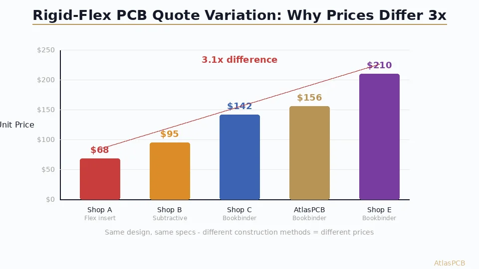
Pricing dramatically below market. Rigid-flex fabrication has real cost floors driven by material cost (polyimide is 3-5x FR-4 price), low panel utilization (flex outlines waste material), and higher scrap rates. A manufacturer pricing 40% below established competitors is either accepting very low yield (passing cost to you through quality issues) or using inferior materials.
Lead times identical to standard rigid. Complex rigid-flex requires 50-100% longer fabrication time than equivalent-layer-count rigid boards due to multiple lamination cycles, coverlay processing, and controlled-depth routing. If quoted lead time does not reflect this, the manufacturer may be under-estimating process complexity.
No cycle-life test data for dynamic flex. If your application involves repeated bending and the manufacturer cannot provide cycle-life test data from similar constructions, they have not validated their process for dynamic flex. This is a reliability risk that manifests in the field, not in prototype testing.
Qualification Process
Before committing production volume to a new rigid-flex manufacturer, a structured qualification process protects your investment:
Phase 1: Capability Verification
- Review manufacturer’s rigid-flex portfolio (completed designs at similar complexity)
- Verify material certifications and supplier relationships
- Review process control documentation (SPC data on key parameters)
- Inspect facility for flex-specific equipment and environmental controls
Phase 2: Test Vehicle Build
- Submit a test vehicle design that exercises your critical features
- Review first-article inspection results including cross-sections
- Evaluate impedance control, copper thickness uniformity, and registration data
- Perform bend testing to verify radius compliance and reliability
Phase 3: Production Verification
- Run initial production lot (5-10 panels)
- Track yield per process step
- Verify repeatability across multiple production dates
- Confirm packing and handling procedures preserve flex integrity
This process typically takes 6-8 weeks. Budget for it in your program schedule. Attempting to skip qualification and go directly to production with an unproven rigid-flex supplier is the highest-risk decision in the PCB procurement chain.
What AtlasPCB Offers for Rigid-Flex
Our rigid-flex capability has been developed through thousands of production builds across medical devices, wearables, aerospace, and industrial applications:
- Layer count: 2-22 layers, up to 4 independent flex zones
- Flex types: single-sided, double-sided, and multilayer flex sections
- Materials: Kapton, adhesiveless PI, LCP; acrylic and epoxy adhesive systems
- Bend radius: 3mm minimum for static (0.1mm single-layer flex), 6mm for dynamic
- Dynamic flex: validated to 500,000+ cycles on standard constructions
- Controlled-depth routing: ±50μm Z-axis tolerance with laser feedback
- Impedance control: ±10% on flex layers, ±8% on rigid sections
- Certifications: IPC-2223 Type 3/4, IPC-6013 Class 3
Every rigid-flex order receives engineering review by staff specializing in flex circuit design rules. We verify your transition zone geometry, bend radius compliance, material compatibility, and impedance achievability before fabrication begins — catching issues that would otherwise become expensive scrap or, worse, field failures.
The goal is not just delivering boards that work in prototype — it is delivering a design and process combination that scales to production volume with predictable yield.
About AtlasPCB — We specialize in complex PCB manufacturing for HDI, RF, and high-reliability applications. Explore our rigid-flex PCB manufacturing, or get an full PCB manufacturing capabilities . Every order includes free engineering review. Get your quote.
Reviewed by AtlasPCB Engineering Team — IPC-certified manufacturing specialists with 15+ years of production experience in HDI, RF, and high-reliability PCB fabrication. Content based on factory floor data and real customer design reviews.
Frequently Asked Questions
What qualifies a manufacturer to produce rigid-flex PCBs?
How do I verify a rigid-flex manufacturer's bend radius capability?
What is the difference between adhesive-based and adhesiveless rigid-flex construction?
Why do some rigid-flex manufacturers have much higher pricing than others?
How many layers can rigid-flex PCBs have?
- rigid flex PCB manufacturer
- rigid-flex PCB
- flex-rigid PCB
- polyimide PCB
- rigid flex fabrication
- IPC-2223
- bend radius
- dynamic flex