· AtlasPCB Engineering Team · Materials · 14 min read
Polyimide PCB Materials for High-Temperature Applications: Automotive Under-Hood, Downhole, and Aerospace Environments
Polyimide laminates maintain mechanical and electrical properties at 260 degrees Celsius continuous operation, making them essential for automotive engine controls, oil well logging tools, and aerospace avionics where standard FR-4 fails within hours.
The Temperature Ceiling of Standard FR-4 and Why It Matters
Standard FR-4 laminate, the workhorse of the PCB industry for over four decades, carries a glass transition temperature (Tg) between 130 and 180 degrees Celsius depending on the specific resin system. Above Tg, the epoxy matrix softens, the coefficient of thermal expansion (CTE) in the Z-axis increases by 3x to 5x, and mechanical strength degrades rapidly. For a circuit board operating continuously at 150 degrees Celsius, a standard Tg 170 FR-4 like Isola 370HR begins showing measurable property degradation within 2000 hours. In applications where ambient temperatures routinely reach 200 to 300 degrees Celsius, such as the engine compartment of an internal combustion vehicle or the downhole section of an oil well at 4000 meters depth, FR-4 simply cannot survive.
Polyimide materials fill this critical performance gap. With glass transition temperatures exceeding 250 degrees Celsius and continuous operating ratings of 260 degrees Celsius per IPC-4101/40 slash sheet requirements, polyimide laminates maintain their mechanical integrity, dimensional stability, and electrical performance where epoxy-based materials have already failed. At our facility, polyimide boards represent approximately 8 percent of total production volume but account for some of our most demanding manufacturing challenges due to the material’s unique processing requirements. Understanding when and how to specify polyimide can mean the difference between a field failure at 6 months and reliable operation past 20 years.
Polyimide Resin Chemistry and Thermal Stability Mechanisms
Polyimide derives its exceptional thermal stability from the imide ring structure in its polymer backbone. The aromatic imide groups create rigid, planar molecular segments that resist rotational freedom and thermal decomposition at temperatures where aliphatic epoxy chains would already be breaking apart. The thermal decomposition temperature (Td) of polyimide laminates typically exceeds 390 degrees Celsius, compared to 310 to 340 degrees Celsius for high-Tg FR-4 systems. This 50-to-80-degree advantage in decomposition onset provides a substantial safety margin for applications in the 200 to 300 degree range.
DuPont’s Kapton polyimide film, first commercialized in 1965, established the foundation for polyimide PCB technology. Today, laminate manufacturers including Isola (P95 and P96 systems), Arlon (an AGC company with their 85N and 35N product lines), and Shengyi Technology (SP series) offer woven glass-reinforced polyimide laminates in standard thicknesses from 0.05mm to 3.2mm. The base polyimide resin is reinforced with E-glass or S-glass fabric to provide dimensional stability and mechanical strength, with resin content typically between 45 and 65 percent by weight. Unlike epoxy systems that cure through a one-time crosslinking reaction, polyimide undergoes an imidization reaction during lamination that creates the fully aromatic ring structure responsible for its thermal performance.
Dielectric Properties at Elevated Temperatures
One of polyimide’s most critical advantages over FR-4 appears in its dielectric property stability across temperature. Standard FR-4 shows a dielectric constant (Dk) increase of 8 to 12 percent when temperature rises from 25 to 150 degrees Celsius, primarily due to increased molecular mobility in the epoxy matrix. Polyimide laminates, by contrast, exhibit Dk variation of only 2 to 4 percent across the same temperature range, with values remaining stable out to 250 degrees Celsius. For circuits operating in variable thermal environments, this stability simplifies impedance design because the characteristic impedance variation stays within plus or minus 3 percent across the full operating temperature range.
The dissipation factor (Df) of polyimide at 1 GHz typically measures 0.008 to 0.012, compared to 0.015 to 0.025 for standard FR-4. While polyimide is not a low-loss material suitable for millimeter-wave applications (where PTFE or LCP excel), its moderate loss performance combined with temperature stability makes it ideal for sensor interfaces, motor controllers, and power conversion circuits operating at frequencies below 5 GHz. Isola’s P96 polyimide specifies Dk of 4.2 and Df of 0.009 at 1 GHz per IPC-TM-650 method 2.5.5.5, measured at room temperature, with less than 5 percent variation up to 200 degrees Celsius. This predictable electrical behavior simplifies design validation for automotive engineers who must certify operation across the minus 40 to plus 175 degree Celsius qualification range specified in AEC-Q100 Grade 0.
Z-Axis CTE and Plated Through-Hole Reliability
The Z-axis coefficient of thermal expansion determines whether plated through-holes and vias will survive thermal cycling in high-temperature applications. Below Tg, standard FR-4 exhibits Z-axis CTE of approximately 50 to 70 ppm per degree Celsius. Above Tg, this value jumps to 250 to 350 ppm per degree Celsius, imposing enormous strain on copper barrel plating during each thermal excursion. For a 1.6mm board cycling from 25 to 200 degrees Celsius with a Tg 170 FR-4, the Z-axis expansion above Tg contributes roughly 10 micrometers of additional strain per cycle, a value that exceeds the fatigue endurance of 25-micrometer copper plating within 500 to 1000 cycles.
Polyimide’s Tg above 250 degrees Celsius means the board never enters the high-CTE regime during normal operation at 200 degrees. The below-Tg Z-axis CTE of polyimide laminates measures 40 to 55 ppm per degree Celsius, slightly lower than FR-4, and this consistent value applies across the entire operational temperature range. Our reliability testing data shows that polyimide boards with 25-micrometer copper plating survive greater than 3000 thermal cycles from minus 55 to plus 200 degrees Celsius without barrel crack failures, compared to failure onset at 200 to 400 cycles for high-Tg FR-4 under the same conditions. IPC-TM-650 method 2.6.26 (Interconnect Stress Testing) validates this performance, with polyimide boards consistently exceeding the 500-cycle minimum required for IPC-6012 Class 3 qualification at elevated temperature.
Automotive Under-Hood Applications and AEC Qualification
Modern vehicles contain 50 to 100 electronic control units (ECUs), with approximately 15 to 20 located within the engine compartment where temperatures reach 125 to 175 degrees Celsius during normal operation and can spike to 200 degrees during extreme conditions. Transmission controllers, exhaust gas recirculation (EGR) valve drivers, turbocharger actuators, and direct fuel injection modules all require PCB materials rated for continuous operation above 150 degrees Celsius. While some designs address this requirement with remote-mounted electronics and thermal insulation, the trend toward integrated smart actuators places the electronics directly on the component, eliminating wiring harness weight and improving response times.
Continental AG, Bosch, and Denso all specify polyimide substrates for their hot-zone ECU platforms. The qualification path follows AEC-Q200 for passive components and internal reliability standards that typically require 1000 thermal cycles at minus 40 to plus 175 degrees Celsius per JEDEC JESD22-A104. At our production facility, automotive polyimide boards undergo 100 percent electrical testing per IPC-9252, followed by microsection analysis on 3 coupons per panel lot. The bare board undergoes SIR (Surface Insulation Resistance) testing per IPC-TM-650 method 2.6.3.7 at 85 degrees Celsius and 85 percent relative humidity for 168 hours, with resistance values required to remain above 100 megohms. This testing regime catches both material defects and contamination issues that could lead to field failures in the harsh automotive environment.
Downhole Oil and Gas Electronics: 175 to 300 Degrees Celsius
The oil and gas industry pushes PCB temperature requirements to their absolute limits. Measurement while drilling (MWD) and logging while drilling (LWD) tools operate at depths where formation temperatures reach 175 to 225 degrees Celsius in conventional wells and 250 to 300 degrees Celsius in high-pressure, high-temperature (HPHT) geothermal wells. These tools must function continuously for 200 to 500 hours per run at temperature, with no possibility of repair or replacement until the tool string is retrieved to the surface. The combination of extreme temperature, mechanical vibration from the drill string (10 to 50 g random vibration), and hydrostatic pressure exceeding 200 MPa creates one of the harshest operating environments for printed circuit boards.
Standard polyimide laminates with Tg of 260 degrees Celsius serve applications up to approximately 225 degrees Celsius continuous operation. Beyond this point, specialty materials such as Arlon’s 85N (rated to 250 degrees Celsius) or advanced bismaleimide triazine (BT) polyimide blends extend the range. For the most extreme downhole applications above 275 degrees Celsius, ceramic-on-polyimide hybrid substrates or LTCC (Low Temperature Co-fired Ceramic) replace organic PCBs entirely. Halliburton, Schlumberger (now SLB), and Baker Hughes each maintain approved material lists for their downhole electronics, typically requiring 1000-hour life testing at maximum rated temperature before qualification. We manufacture MWD tool boards using Isola P96 polyimide with 2-ounce copper on 8-layer constructions, processing approximately 40 to 60 panels per month for the energy sector. The most critical manufacturing consideration for these boards is moisture removal before lamination, as polyimide absorbs 1.5 to 3.0 percent moisture by weight compared to 0.3 percent for FR-4.
Aerospace and Defense: Thermal Cycling with Altitude Pressure Changes
Aerospace PCB applications combine high temperature exposure with rapid thermal cycling and reduced atmospheric pressure. A radar system in a fighter aircraft nose cone experiences temperatures from minus 65 degrees Celsius at altitude to plus 200 degrees Celsius near the radar transmitter during operation, with transition rates exceeding 10 degrees per minute during rapid climb or descent. At altitude, reduced air pressure (as low as 10 kPa at 50,000 feet) eliminates convective cooling and can trigger outgassing from laminate materials, potentially contaminating sensitive optical or RF components.
Polyimide’s low outgassing characteristics make it the preferred material for space-adjacent and vacuum-exposed applications. Per ASTM E595 testing, polyimide laminates show total mass loss (TML) below 0.5 percent and collected volatile condensable materials (CVCM) below 0.05 percent, well within NASA’s requirements for spacecraft hardware. The mil-spec designation for polyimide PCBs falls under MIL-PRF-31032 and the older MIL-P-13949 Type GI (glass-reinforced polyimide), with qualification testing per IPC-6012 Class 3/A (space addendum) requiring thermal cycling from minus 65 to plus 260 degrees Celsius. Lockheed Martin, Northrop Grumman, and Raytheon (RTX) all maintain qualified polyimide PCB sources on their approved vendor lists, with typical qualification timelines running 6 to 12 months from initial capability audit to full production authorization.
Manufacturing Challenges: Drilling, Lamination, and Moisture Control
Polyimide presents distinct manufacturing challenges compared to standard FR-4 processing. The material’s toughness and abrasion resistance, while advantageous in service, make mechanical drilling more difficult. Drill bit life decreases by 30 to 50 percent compared to FR-4 drilling, with typical polyimide hit counts of 1500 to 2500 holes per drill bit versus 3000 to 5000 for FR-4. Drill spindle speeds must increase to 150,000 to 180,000 RPM with reduced feed rates of 1.0 to 1.8 meters per minute to prevent delamination at the hole wall. Drill bit selection shifts toward micro-grain carbide substrates with higher cobalt binder content (10 to 12 percent) for improved wear resistance.
Lamination of polyimide multilayers requires higher temperatures and longer cure cycles than FR-4 processing. While FR-4 lamination peaks at 180 to 190 degrees Celsius for 60 to 90 minutes, polyimide requires 200 to 230 degrees Celsius for 90 to 150 minutes to achieve full imidization of the resin system. Lamination pressure must be carefully controlled between 200 and 400 psi to achieve proper resin flow without excessive squeeze-out. Perhaps the most critical manufacturing concern is moisture management. Polyimide’s hygroscopic nature means that prepregs and core materials absorb ambient moisture rapidly, with equilibrium moisture content reaching 1.5 percent at 50 percent relative humidity. Absorbed moisture volatilizes during lamination, creating delamination, blisters, and measling defects. Our standard procedure requires baking all polyimide materials at 105 degrees Celsius for 4 hours minimum before layup, with a maximum 2-hour window between bake completion and lamination press loading.
Cost Comparison: Polyimide vs FR-4 and When the Premium Is Justified
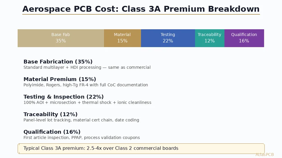
Polyimide raw material costs run 3x to 5x higher than equivalent FR-4 laminates. A standard 18x24 inch panel of 0.1mm polyimide core costs approximately 85 to 120 dollars compared to 20 to 35 dollars for high-Tg FR-4. This material cost premium, combined with longer drilling cycles, extended lamination times, and additional baking steps, results in finished board costs typically 2.5x to 4x higher than equivalent FR-4 constructions. An 8-layer polyimide board with 1.6mm thickness might cost 45 to 75 dollars per piece in quantities of 100, compared to 15 to 25 dollars for the same design in FR-4.
The cost premium is justified when the application genuinely requires continuous operation above 150 degrees Celsius or when thermal cycling spans exceed 200 degrees (such as minus 55 to plus 175 degrees Celsius military qualification). For applications with peak temperatures below 130 degrees Celsius, standard FR-4 provides adequate performance at dramatically lower cost. The gray zone between 130 and 170 degrees Celsius is where material selection requires careful engineering judgment. High-Tg FR-4 options like Isola 370HR (Tg 180 degrees Celsius) or Panasonic Megtron 4 (Tg 175 degrees Celsius) may provide sufficient margin without the full polyimide cost penalty. We routinely advise customers on this decision, analyzing their thermal profile data against material capability curves to identify the most cost-effective solution. In roughly 30 percent of cases where customers initially specify polyimide, our engineering review identifies that a high-Tg FR-4 with proper thermal management will meet their reliability requirements at 40 to 60 percent lower board cost.
Design Guidelines for Polyimide PCBs
Designing for polyimide manufacturing requires adjustments to standard FR-4 design rules. Minimum trace width and spacing can match FR-4 capabilities (typically 3/3 mil for inner layers and 3.5/3.5 mil for outer layers), but annular ring requirements should increase by 1 to 2 mils to accommodate the material’s higher drilling registration tolerance. Pad-to-drill ratio should be at least 1.8:1 for through-holes, compared to 1.5:1 acceptable in standard FR-4. This additional annular ring compensates for slightly greater hole position tolerance caused by the tougher material’s resistance to drill entry.
Via aspect ratios should be limited to 8:1 for mechanically drilled holes in polyimide, compared to 10:1 commonly achieved in FR-4. The material’s resistance to desmear chemicals requires plasma desmear rather than permanganate chemical desmear for holes with aspect ratios above 6:1. For solder mask, standard LPI (liquid photoimageable) masks such as Taiyo PSR-4000 AUS703 maintain adhesion to polyimide surfaces, but the polyimide’s smooth surface finish may require additional surface preparation (light pumice scrub or chemical micro-etch) to achieve the 0.8 to 1.2 micrometer Ra roughness needed for optimal mask adhesion. When specifying polyimide boards, designers should include explicit notes on the fabrication drawing referencing IPC-4101/40 or /41 slash sheets and specifying the Tg and Td requirements to prevent substitution with lower-grade materials.
Reliability Testing and Qualification Protocols for High-Temperature PCBs
Qualifying a polyimide PCB design for high-temperature service requires a comprehensive test program beyond standard IPC-6012 requirements. The qualification sequence typically begins with thermal cycling per IPC-TM-650 method 2.6.7.2, with temperature extremes matching or exceeding the intended application range. For automotive applications, 1000 cycles at minus 40 to plus 175 degrees Celsius with 15-minute dwell times and 5-minute transitions represents the industry standard. Acceptance criteria include no barrel cracks visible at 200x magnification, less than 10 percent resistance increase in daisy-chain test coupons, and no delamination per IPC-TM-650 method 2.4.8.
Beyond thermal cycling, high-temperature PCBs undergo time-at-temperature testing where boards operate continuously at maximum rated temperature for 1000 to 5000 hours. Measurements taken at 250-hour intervals track insulation resistance between conductors (minimum 100 megohms required), dielectric withstanding voltage (must exceed 500V/mil), and dimensional stability (maximum 0.1 percent change per axis). Conductive anodic filament (CAF) testing per IPC-TM-650 method 2.6.25 becomes especially important at elevated temperatures because ion mobility increases with temperature, accelerating electrochemical migration between closely spaced conductors. We maintain a dedicated environmental testing lab with 4 thermal cycling chambers and a burn-in oven capable of sustaining 300 degrees Celsius for our qualification programs, processing approximately 150 qualification lots per year for customers entering automotive and energy market segments.
Reviewed by AtlasPCB Engineering Team
Need High-Temperature PCBs for Demanding Applications?
Our materials team helps you select the right polyimide system for your operating environment and qualification requirements. Free DFM review included.
Get Your Quote →About AtlasPCB — We specialize in complex PCB manufacturing for HDI, RF, and high-reliability applications. Explore our rigid-flex PCB manufacturing, or get an full PCB manufacturing capabilities . Every order includes free engineering review. Get your quote.
Reviewed by AtlasPCB Engineering Team — IPC-certified manufacturing specialists with 15+ years of production experience in HDI, RF, and high-reliability PCB fabrication. Content based on factory floor data and real customer design reviews.
- polyimide PCB
- high temperature materials
- automotive PCB
- aerospace electronics
- DuPont Kapton
- IPC-4101