· AtlasPCB Engineering · Engineering · 10 min read
Medical Device PCB Requirements: IEC 60601, Creepage, and Reliability Standards You Cannot Skip
A manufacturing-focused guide to PCB requirements for medical devices. Covers the specific fabrication parameters driven by IEC 60601 safety standards, FDA device classification, creepage/clearance rules, material qualifications, and reliability testing requirements that determine whether your PCB passes regulatory review.
The Regulatory Framework: How Standards Cascade to PCB Requirements
Medical device PCB requirements do not exist in a single standard — they cascade from multiple regulatory frameworks that each impose specific constraints on the physical PCB. Understanding this cascade helps you identify which requirements apply to your specific device and avoid both over-engineering (wasting cost) and under-engineering (failing regulatory review).
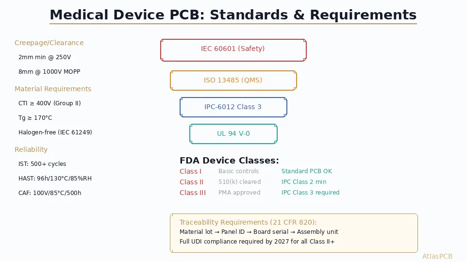
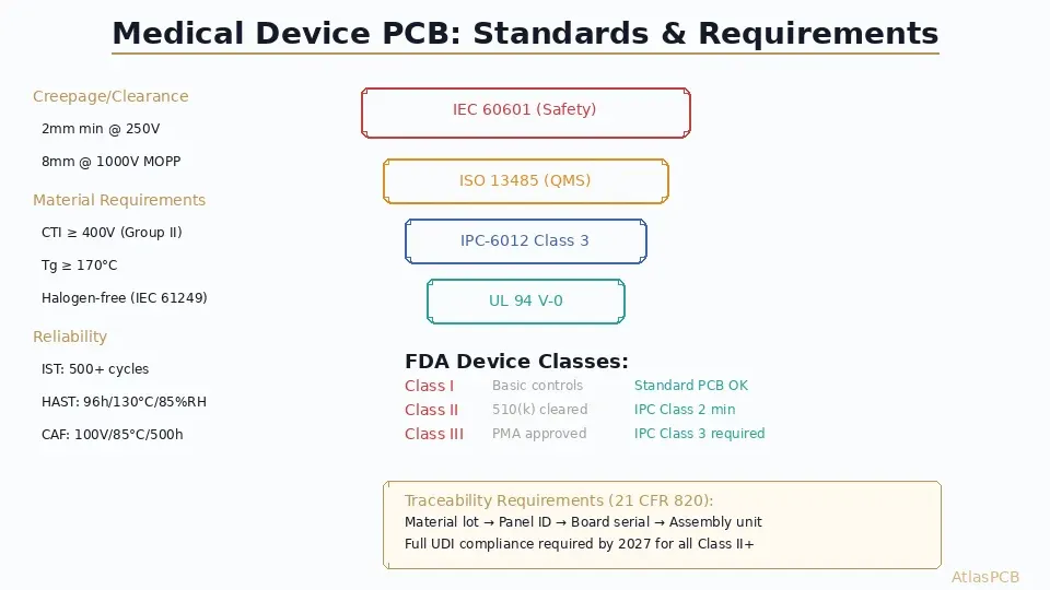
The hierarchy works like this: FDA device classification determines which safety standards apply. IEC 60601-1 (the primary medical electrical equipment safety standard) drives creepage, clearance, and dielectric withstand requirements that affect PCB layout. ISO 13485 (quality management) imposes traceability and process validation requirements on the PCB manufacturer. IPC-6012 (PCB qualification and performance) provides the fabrication acceptance criteria that ensure physical reliability.
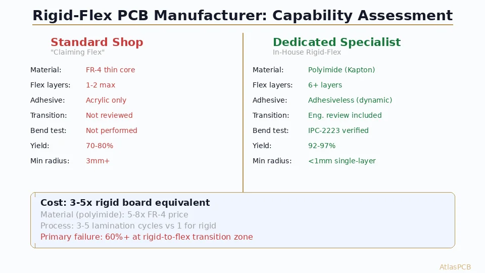
Most PCB manufacturers claiming “medical capability” focus only on IPC-6012 Class 3 fabrication — but this addresses only the physical quality of the board, not the regulatory documentation, material certification, or design compliance that medical device companies actually need verified.
MEDICAL PCB MANUFACTURING
IPC-6012 Class 3 with Full Traceability
We manufacture medical-grade PCBs with ISO 13485 traceability, UL-listed materials, and reliability qualification testing. Documentation package supports FDA 510(k) and CE marking submissions.
IEC 60601-1: The Requirements That Affect Your PCB Layout
IEC 60601-1 is the international safety standard for medical electrical equipment. Its requirements cascade into PCB design primarily through creepage, clearance, and dielectric withstand specifications that are significantly more stringent than standard electronics.
Creepage and Clearance
Creepage is the shortest distance between two conductive parts measured along the surface of insulation. Clearance is the shortest distance through air. For medical devices, these distances are defined by Means of Protection (MOP):
| Insulation Level | Working Voltage | Min Clearance | Min Creepage |
|---|---|---|---|
| 1x MOPP (basic) | 250V rms | 2.5mm | 4.0mm |
| 2x MOPP (reinforced) | 250V rms | 5.0mm | 8.0mm |
| 1x MOOP (operator) | 250V rms | 2.5mm | 5.0mm |
| 2x MOOP (reinforced) | 250V rms | 5.0mm | 8.0mm |
These distances apply between patient-connected circuits and all other circuits — including ground planes. On a PCB, this means wide isolation gaps (5-8mm) that fragment your ground plane topology and create EMC challenges. The design tension between safety creepage and EMC performance is one of the central engineering challenges in medical PCB design.
In our production experience, the most common PCB-level issue we see in medical designs is inadequate creepage distance where a ground plane or power plane extends too close to the isolation boundary. The designer accounts for trace-to-trace distance but forgets that the internal plane layers must also respect creepage requirements at every point where the plane approaches an isolated circuit.
Dielectric Withstand
IEC 60601-1 requires the PCB to withstand specific test voltages without breakdown. For reinforced insulation at 250V working voltage, the test voltage is 4000V AC for 1 minute. This means the PCB laminate between isolated circuits must not breakdown at this voltage — requiring material with adequate dielectric strength and sufficient thickness between layers carrying isolated circuits.
Standard FR-4 provides approximately 800V/mil dielectric strength (new material, room temperature). After aging and humidity exposure, this degrades to 500-600V/mil. For 4000V withstand, minimum laminate thickness between isolated layers must be at least 8mil — preferably 12-15mil for margin. This affects your stackup design: the isolation barrier layer cannot be a thin prepreg.
Material Requirements Specific to Medical PCBs
CTI (Comparative Tracking Index)
IEC 60601-1 requires materials with CTI values appropriate for the pollution degree of the device’s internal environment. Most medical devices operate in Pollution Degree 2 (non-conductive contamination expected). For PD2 with reinforced insulation, laminate material must achieve CTI ≥ 400V (Material Group II or better).
Standard FR-4 from major suppliers typically achieves CTI 175-250V (Group IIIb) — which is insufficient for many medical applications without additional creepage distance compensation. High-CTI laminates (CTI ≥ 600V, Group I) are available from Isola (DE104), ITEQ (IT-180A+), and others, but must be specifically requested and verified via material certificate.
This is a detail many medical device companies miss until EMC testing or safety review: their prototype was built on standard FR-4 with adequate creepage for Group IIIb material, but production material substitution to a lower CTI grade violates the creepage calculation. Locking material specification to a specific CTI-qualified grade in your procurement documentation prevents this failure mode.
Halogen-Free Requirements
IEC 61249-2-21 defines halogen-free PCB materials (chlorine ≤ 900ppm, bromine ≤ 900ppm, total halogens ≤ 1500ppm). While not strictly required by IEC 60601-1, many medical device companies require halogen-free materials for environmental compliance (RoHS recast, EU MDR environmental considerations) and reduced toxic gas generation in fire scenarios.
Halogen-free FR-4 costs 8-15% more than standard material and processes slightly differently (different moisture absorption, slightly different drill parameters). Ensure your manufacturer has characterized their process for the specific halogen-free laminate grade you specify.
MATERIAL SOURCING
Medical-Grade Laminates with Full Certification
We source UL-listed, high-CTI, halogen-free laminates from Isola, ITEQ, and Shengyi with material certificates and lot traceability for every order. No material substitution without customer approval.
Specify Medical Materials ›IPC-6012 Class 3: What It Actually Means for Fabrication
IPC-6012 Class 3 (High Reliability) imposes specific fabrication requirements beyond standard Class 2 construction:
Annular ring: Minimum 5mil on all layers (external and internal). Class 2 allows 4mil internal. This affects via design — your drill-to-pad calculation must accommodate Class 3 minimums plus manufacturing tolerance.
Conductor width reduction: Maximum 20% from design nominal (Class 2 allows 30%). This means tighter etch control and potentially modified etch compensation — directly affecting cost.
Plating thickness: Minimum 1mil (25μm) copper in plated through-holes. Class 2 allows 0.8mil (20μm). The additional plating time adds 10-15% to the plating process step.
Surface defects: No lifted pads, no measling, no crazing in Class 3. Class 2 allows these in non-functional areas. This means higher rejection rates during visual inspection — typically reducing yield by 3-5%.
Cross-sectioning: Class 3 requires cross-section evaluation with minimum 2 per lot (where Class 2 allows inspection per the quality plan). This adds $50-100 per lot in testing cost but provides documented evidence of internal quality.
The practical cost impact of Class 3 versus Class 2 fabrication is typically 15-25% higher board cost, driven primarily by tighter process control, additional inspection, higher rejection rates, and documentation requirements.
Traceability: The Documentation Your Regulatory Submission Needs
FDA 21 CFR Part 820 (Quality System Regulation) and ISO 13485 require documented traceability from raw materials through finished product. For PCBs, this means your manufacturer must provide:
Material traceability: Laminate manufacturer, grade, lot number, and date code for every material in your board. Rogers RO4350B lot 25-4421 manufactured March 2026, with material certificate showing Dk within ±0.04 of specification. Copper foil: Mitsui TQ-VLP, lot number, purity certification.
Process traceability: Panel identification linking your specific boards to a defined manufacturing batch. Which press cycle, what lamination parameters were used, which plating bath, what chemistry conditions. This allows root cause analysis if a field failure occurs.
Inspection records: AOI results, electrical test results, dimensional measurements, and any cross-section data — all linked to the panel ID for your specific boards.
Operator traceability: At critical process steps (lamination, laser drill, plating, final inspection), identification of which certified operator performed the work.
Not all PCB manufacturers maintain this level of documentation. Standard consumer-electronics fabrication often uses batch-level tracking (hundreds of different customer boards processed in the same batch) without individual panel tracing. Medical-grade fabrication requires individual panel identification from raw material receipt through shipment.
REGULATORY SUPPORT
Documentation Package for FDA/CE Submissions
Our medical PCB documentation package includes material certificates, process traceability, cross-section reports, reliability test data, and conformance certificates — formatted for direct inclusion in 510(k) or CE technical files.
Request Documentation Package ›Reliability Testing: What to Qualify Before Production
For medical devices with patient contact or life-critical function, reliability qualification testing provides evidence that the PCB will survive its intended service life. Testing should be performed on production-representative samples (same material, same process, same manufacturer) during design validation.
IST (Interconnect Stress Testing): Rapidly thermal-cycles a test coupon using internal Joule heating. More aggressive than oven thermal cycling because it tests the barrel-to-pad interface directly. Minimum 500 cycles without >10% resistance change demonstrates adequate reliability for most medical applications. For implantable devices, 1000+ cycles is typical.
Thermal Cycling: IPC-TM-650 2.6.7.2 at -55C to +125C (or application-specific range). Medical devices that experience autoclaving (134C for 18 minutes) must test at ranges exceeding autoclave temperature. Minimum 200 cycles for non-life-support, 500+ cycles for life-support applications.
CAF Testing: Conductive Anodic Filament testing per IPC-TM-650 2.6.25 verifies that electrochemical migration does not create shorts between adjacent conductors under humidity and bias. Critical for medical devices operating in humid environments or those with tight conductor spacing (<15mil). Pass criteria: no resistance drop below 100M ohm after 500 hours at 85C/85%RH with 50V bias.
Practical Guidance: Matching PCB Requirements to Device Class
Not every medical device needs the full spectrum of requirements. Match your PCB specification to your actual regulatory and clinical risk:
FDA Class I (General Controls): IPC-6012 Class 2 is often acceptable. Standard FR-4 with basic traceability. No special reliability testing required unless the device has patient contact. Examples: tongue depressors, elastic bandages, examination gloves.
FDA Class II (Special Controls, 510(k)): IPC-6012 Class 3 recommended. High-Tg FR-4 minimum, CTI-qualified material if isolation boundaries exist. IST or thermal cycle qualification recommended. Full material and process traceability required. Examples: powered wheelchairs, infusion pumps, patient monitors.
FDA Class III (PMA): IPC-6012 Class 3 mandatory. Material qualification including aging and humidity studies. IST, thermal cycling, and CAF testing required. Complete traceability with operator identification. Cross-section documentation for every production lot. Examples: implantable pacemakers, cochlear implants, artificial hearts.
ATLASPCB
Medical Device PCB Manufacturing — Class 2 and Class 3
IPC-6012 Class 3 fabrication with ISO 13485 traceability, UL-listed materials, reliability testing support, and regulatory documentation packages. 4 to 30 layers, FR-4 through specialized laminates.
Get Medical PCB Quote ›Reviewed by AtlasPCB Engineering Team — 15+ years in advanced PCB fabrication for RF, HDI, and rigid-flex applications.
Related Reading:
About AtlasPCB — We specialize in complex PCB manufacturing for HDI, RF, and high-reliability applications. Explore our HDI PCB manufacturing capabilities, impedance-controlled PCB manufacturing, or get an full PCB manufacturing capabilities . Every order includes free engineering review. Get your quote.
Reviewed by AtlasPCB Engineering Team — IPC-certified manufacturing specialists with 15+ years of production experience in HDI, RF, and high-reliability PCB fabrication. Content based on factory floor data and real customer design reviews.
- medical device PCB requirements
- PCB manufacturing
- IPC-6012 Class 3
- PCB reliability
- impedance controlled PCB manufacturer
- HDI PCB manufacturer