· AtlasPCB Engineering Team · Materials · 15 min read
High-Tg FR-4 vs Standard FR-4: Thermal Reliability in Lead-Free Assembly
Compare high-Tg and standard FR-4 PCB materials for lead-free soldering applications. Covers glass transition temperature effects on delamination resistance, Z-axis expansion, reflow survivability, and material selection guidelines.
The Thermal Challenge of Lead-Free Assembly on FR-4 Substrates
The transition from tin-lead to lead-free soldering fundamentally changed the thermal demands placed on PCB substrates. Lead-free solder alloys—predominantly SAC305 and its variants—require peak reflow temperatures between 245 and 260 degrees Celsius, roughly 30 to 40 degrees higher than the 215 to 225 degrees used for eutectic tin-lead. This temperature increase pushes standard FR-4 materials into and beyond their glass transition range during every reflow cycle, creating conditions where delamination, measling, and Z-axis expansion damage become probable rather than merely possible.
Standard FR-4 with a glass transition temperature around 130 to 140 degrees Celsius was originally developed for tin-lead assembly processes and performs admirably within that thermal envelope. When subjected to lead-free reflow profiles, however, the material spends significant time above its Tg where the epoxy matrix transitions from a rigid glass-like state to a rubbery condition with dramatically increased thermal expansion coefficient. High-Tg FR-4 formulations with glass transition temperatures of 170 to 180 degrees Celsius maintain their dimensional stability through a substantially larger portion of the reflow cycle, reducing cumulative damage and extending product reliability.
Through our production experience fabricating boards for both leaded and lead-free assembly, we have developed clear guidelines for when standard FR-4 remains adequate and when the investment in high-Tg material becomes essential for long-term product reliability.
Understanding Glass Transition Temperature in Practice
The glass transition temperature represents the point at which the cross-linked epoxy resin in FR-4 transitions from a glassy, rigid state to a softer, more mobile condition. This is not a sharp melting point but rather a gradual transition occurring over a temperature range of approximately 10 to 20 degrees. Below Tg, the resin system restrains the glass fiber reinforcement and maintains dimensional stability. Above Tg, the resin softens, loses its constraining effect, and the material’s coefficient of thermal expansion in the Z-axis (through-thickness direction) increases dramatically—typically by a factor of three to five times.
For standard FR-4 with a Tg of 135 degrees Celsius, the Z-axis CTE below Tg is approximately 50 to 60 parts per million per degree Celsius. Above Tg, this value jumps to 250 to 300 ppm per degree Celsius. The total Z-axis expansion during a reflow cycle from room temperature to 260 degrees depends critically on how much of that temperature excursion occurs above Tg. For standard FR-4, approximately 125 degrees of the heating cycle occurs above Tg, accumulating substantial Z-axis expansion that stresses plated through-holes, vias, and internal layer connections.
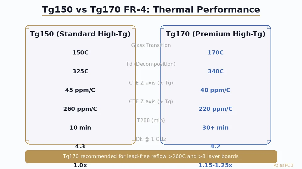
High-Tg FR-4 with a Tg of 170 degrees Celsius reduces the above-Tg temperature excursion during lead-free reflow from 125 degrees down to approximately 90 degrees. Moreover, the below-Tg CTE of high-Tg materials is typically lower—around 40 to 50 ppm per degree Celsius—because the denser cross-linking that creates the higher Tg also constrains thermal expansion more effectively. The combined effect of higher transition temperature and lower base CTE reduces total Z-axis expansion during reflow by 30 to 40 percent compared to standard FR-4.
Z-Axis Expansion and Via Reliability
The Z-axis expansion that occurs during thermal excursions directly stresses the copper plating in through-holes and vias. As the board thickness expands, the copper barrel must stretch to accommodate the dimensional change. Copper’s coefficient of thermal expansion is only 17 ppm per degree Celsius, while the FR-4 in which it is embedded expands at 50 ppm below Tg and 250 ppm above Tg. This mismatch creates tensile strain in the via barrel that accumulates with each thermal cycle.
Via barrel cracking is the primary reliability failure mode driven by Z-axis expansion. The crack typically initiates at the point of maximum stress concentration—usually at the inner layer connection point where the barrel transitions from the plated hole wall to the annular ring pad. Once initiated, the crack propagates with subsequent thermal cycles until electrical continuity is lost. The rate of crack propagation depends directly on the strain magnitude per cycle, which is determined by the Z-axis expansion per thermal excursion.
Our interconnect stress testing data demonstrates the practical impact clearly. Standard FR-4 boards with 1.6 mm thickness and 0.3 mm plated through-holes subjected to IST cycling at 150 degrees Celsius excursion (simulating lead-free reflow stress) typically achieve 300 to 500 cycles before interconnect failure. Identical boards fabricated on high-Tg FR-4 consistently achieve 800 to 1200 cycles under the same conditions—a two to three times improvement in thermal cycling endurance attributable entirely to the material’s reduced Z-axis expansion.
For thin boards below 1.0 mm thickness, the advantage of high-Tg material is less pronounced because total Z-axis expansion is proportional to board thickness. A 0.8 mm board on standard FR-4 may expand only 30 micrometers during reflow, which most via structures can tolerate. Conversely, thick boards above 2.0 mm amplify the Z-axis expansion problem significantly, making high-Tg material nearly mandatory for any board exceeding 2.0 mm total thickness with lead-free assembly requirements.
Delamination Resistance During Reflow
Delamination—the separation of copper layers from the laminate or the separation between prepreg and core layers—represents the catastrophic failure mode that high-Tg materials most effectively prevent. Delamination occurs when internal moisture vaporizes at reflow temperatures, generating steam pressure that exceeds the bond strength between layers. The combination of reduced resin strength above Tg and increased steam pressure at higher lead-free reflow temperatures creates conditions where standard FR-4 boards can delaminate during assembly.
The mechanism proceeds in stages. First, the board absorbs moisture from the ambient environment during storage. Standard FR-4 absorbs approximately 0.15 to 0.20 percent moisture by weight under normal warehouse conditions. During reflow, this moisture migrates to the weakest interfaces—typically between prepreg resin and copper foil treated surfaces. As temperature exceeds 100 degrees Celsius, the moisture begins converting to steam. At reflow peak temperatures, the steam pressure reaches several atmospheres while the resin simultaneously softens above its Tg, reducing its ability to contain the pressure. If the combined effect exceeds the interface bond strength, delamination occurs.
High-Tg materials combat this through multiple mechanisms. The higher cross-link density that creates the elevated Tg also reduces moisture absorption—typically 0.10 to 0.15 percent versus 0.15 to 0.20 percent for standard FR-4. The higher Tg means the resin retains more mechanical strength at peak reflow temperature, providing greater resistance to steam-generated pressure. And the tighter molecular structure reduces moisture diffusion rates, meaning that even boards stored under identical conditions contain less total moisture in high-Tg material.
In our manufacturing experience, the delamination rate during lead-free assembly on standard FR-4 boards exceeding 8 layers is approximately 0.5 to 2 percent when boards are baked appropriately before assembly and 5 to 10 percent when baking is inadequate or skipped. On high-Tg FR-4 under identical conditions, delamination rates drop to below 0.1 percent with proper baking and remain below 1 percent even without pre-baking. This dramatic improvement in process robustness makes high-Tg material the standard recommendation for any multilayer board destined for lead-free assembly.
Measling and Crazing Under Thermal Stress
Measling manifests as white spots or crosses within the FR-4 laminate, visible to the naked eye against a dark background. These defects represent localized separation between the glass fiber weave and the surrounding resin at weave crossover points. While measling does not necessarily indicate functional failure, it reveals that the resin-fiber interface has experienced stress beyond its design limit—a warning that more severe damage may develop under additional thermal cycling.
Crazing is a more severe form of the same mechanism, where the separation propagates along glass fibers rather than remaining localized at crossover points. Crazing can compromise insulation resistance between adjacent conductors and eventually lead to conductive anodic filament growth—a slow short-circuit failure mode where copper migration along the glass-resin interface eventually bridges conductor-to-conductor spacing.
Standard FR-4 subjected to lead-free reflow profiles commonly exhibits measling in thicker board sections, particularly around areas of high thermal mass differential (such as large ground planes adjacent to sparse routing areas). The differential heating creates localized stress concentrations that exceed the resin-fiber bond strength. High-Tg FR-4’s enhanced cross-linking provides stronger resin-fiber adhesion at elevated temperatures, and the reduced time spent above Tg limits the duration during which this bond is at its weakest.
Our quality acceptance criteria for measling follow IPC-A-600 Class 2 or Class 3 requirements depending on the product category. However, we have observed that boards fabricated on high-Tg material rarely exhibit measling even under worst-case assembly conditions, effectively eliminating measling as a concern during receiving inspection and reducing quality-related delays in the production flow.
Thermal Decomposition Temperature: The Other Critical Parameter
While glass transition temperature receives the most design attention, the thermal decomposition temperature (Td) is equally important for lead-free reliability. Td represents the temperature at which the resin system begins irreversible chemical breakdown, measured as the temperature at which 5 percent weight loss occurs during thermogravimetric analysis at a standard heating rate.
Standard FR-4 materials typically show Td values between 300 and 310 degrees Celsius. High-Tg formulations achieve Td values of 325 to 345 degrees Celsius, providing greater margin above the 260 degrees Celsius peak reflow temperature. While neither material reaches its Td during normal reflow, the proximity matters because chemical degradation begins gradually below the formal Td measurement point. Materials with higher Td exhibit less resin degradation per reflow cycle, maintaining their mechanical properties over multiple assembly passes.
For boards requiring two or three reflow cycles—typical for double-sided SMT assembly followed by selective soldering—the cumulative thermal exposure approaches the degradation threshold of standard FR-4. Each reflow cycle causes incremental resin damage that is not recovered upon cooling. High-Tg materials with higher Td tolerance multiple reflow exposures with substantially less cumulative damage, maintaining full mechanical integrity through complex assembly sequences.
In our standard recommendations, boards requiring three or more thermal excursions above 250 degrees (including rework allowances) should specify high-Tg material regardless of other factors. The cumulative degradation from repeated reflow on standard FR-4 measurably reduces long-term reliability even when no visible damage is apparent after assembly.
Material Cost Comparison
The cost premium for high-Tg FR-4 over standard FR-4 is surprisingly modest relative to the reliability improvement it provides. In current market conditions, high-Tg laminate (Tg 170, such as Shengyi S1170 or equivalent) costs approximately 8 to 15 percent more than standard FR-4 (Tg 135-140). For a typical six-layer board of moderate size, this translates to roughly one to three dollars per board at production volumes.
The cost premium originates from the more complex resin chemistry required to achieve higher cross-link density. High-Tg formulations use modified epoxy systems—often incorporating dicyandiamide-hardened multifunctional epoxy resins—that require more expensive raw materials and tighter process control during laminate manufacturing. However, these materials are fully commoditized in the PCB supply chain with multiple qualified sources, so availability and lead time are not differentiating factors.
When evaluating total product cost including assembly yield, the high-Tg premium often pays for itself through reduced delamination rejection, fewer measling disposition activities, and lower field failure rates. For products with any pretense of reliability requirement beyond basic consumer electronics, the material cost increment is trivial compared to the cost of a single assembly line stop for delamination investigation or a single field return for via fatigue failure.
When Standard FR-4 Remains Adequate
Despite the advantages of high-Tg material, standard FR-4 continues to serve a substantial portion of the PCB market appropriately. Designs that meet all of the following criteria can use standard Tg material without reliability concern: total board thickness below 1.2 mm, four or fewer layers, single-sided SMT assembly requiring only one reflow cycle, operating temperature below 85 degrees Celsius ambient, and product lifetime under five years.
Consumer electronics, simple IoT devices, low-cost industrial sensors, and prototype boards all fall within this envelope. The standard FR-4 material system is the most thoroughly characterized substrate in the industry with the deepest supply chain, the most competitive pricing, and the broadest fabricator capability. For applications within its performance envelope, standard FR-4 provides excellent value.
Standard FR-4 is also appropriate when the board will be assembled using tin-lead solder processes. The lower reflow temperature of tin-lead (peak 215-225 degrees Celsius) means that standard Tg material never approaches its glass transition during assembly, maintaining full dimensional stability and mechanical strength throughout the process. For military and aerospace applications that still permit tin-lead solder under exemption, standard FR-4 may be adequate if the operating temperature requirements are modest.
When High-Tg Material Becomes Essential
High-Tg FR-4 should be specified when any of the following conditions apply. First, board thickness exceeds 1.6 mm with lead-free assembly. The combination of thick board and high-temperature reflow creates Z-axis expansion that standard FR-4 cannot tolerate without via reliability compromise. Most six-layer and above boards in standard 1.6 mm thickness already meet this threshold.
Second, the assembly process requires multiple reflow cycles. Double-sided SMT boards receive minimum two reflow passes, and boards with package-on-package or stacked die configurations may see three or more exposures. Each additional reflow cycle on standard FR-4 accumulates damage that degrades long-term reliability.
Third, the operating environment subjects the board to repeated thermal cycling above 100 degrees Celsius. Automotive under-hood electronics, industrial motor drives, power supply modules, and LED lighting all operate at elevated temperatures where the proximity to standard Tg creates ongoing reliability risk during thermal transients.
Fourth, the product lifetime requirement exceeds five years in field service. Long-life products accumulate thermal cycles from power cycling, environmental temperature variation, and seasonal changes. Over a ten-year service life, even moderate temperature cycling can cause via fatigue on standard FR-4 where high-Tg material would survive indefinitely.
Fifth, the design includes HDI features such as microvias or blind vias. These fine structures are more susceptible to Z-axis expansion damage than conventional through-holes because their smaller barrel diameter provides less copper cross-section to absorb strain. HDI designs should default to high-Tg material unless specifically analyzed and validated for standard Tg.
Process Considerations in Fabrication
From the fabrication perspective, high-Tg materials process very similarly to standard FR-4 with modest adjustments to lamination parameters. The higher Tg resin system requires slightly elevated lamination temperatures (typically 185 to 190 degrees Celsius versus 175 to 180 degrees for standard FR-4) and somewhat longer cure times to ensure complete cross-linking. Drilling parameters may require adjustment because the harder resin increases drill wear slightly, though this effect is minor compared to the copper weight impacts discussed in heavy copper applications.
Etching, imaging, plating, and surface finishing processes are identical between standard and high-Tg FR-4—the material difference affects only the organic resin properties and does not change the copper processing requirements. This means that switching from standard to high-Tg material does not require different manufacturing equipment or significantly different processing routes, keeping the cost impact limited to the raw material premium and minor lamination time adjustments.
One practical consideration is material qualification and traceability. High-reliability programs typically require that the specific laminate grade and manufacturer be documented on the fabrication drawing, with any substitution requiring written customer approval. We maintain qualified sources for multiple high-Tg material brands (Shengyi S1170, TUC TU-872, ITEQ IT-180A) and can provide material certifications and lot traceability as required for automotive, medical, or aerospace applications.
Practical Selection Guidelines
For engineers making the material selection decision, we recommend a simple threshold approach. If the board will be assembled with lead-free solder and meets any one of the following criteria, specify high-Tg FR-4 (Tg greater than or equal to 170 degrees Celsius): thickness at or above 1.6 mm, six or more layers, double-sided SMT assembly, operating temperature above 85 degrees Celsius, product lifetime exceeding five years, or HDI construction.
For boards below these thresholds, standard FR-4 provides adequate performance at lower cost. When in doubt, the conservative choice is always high-Tg—the modest cost premium provides insurance against thermal reliability issues that are difficult to diagnose after the product ships.
Specifying the material in fabrication documentation should include both the Tg requirement and the Td requirement. A typical specification reads: “FR-4, Tg greater than or equal to 170 degrees Celsius (DSC), Td greater than or equal to 340 degrees Celsius (TGA 5 percent weight loss), per IPC-4101/126 or /129.” This ensures the fabricator selects an appropriate material grade that satisfies both thermal parameters.
Conclusion
The choice between standard and high-Tg FR-4 represents one of the most straightforward reliability decisions in PCB design—a modest material cost increase delivers substantial improvement in thermal cycling endurance, delamination resistance, and long-term field reliability. For the vast majority of modern electronics assembled with lead-free solder processes, high-Tg FR-4 has become the de facto standard material rather than a premium option, reflecting the industry’s recognition that the thermal demands of lead-free assembly exceed what original FR-4 formulations were designed to withstand.
Designers who specify materials thoughtfully based on their product’s thermal environment and lifetime requirements—rather than defaulting to whatever was used on the last project—gain a reliability advantage that manifests in lower field failure rates, more robust manufacturing yields, and greater confidence in product qualification testing. When the cost difference between standard and high-Tg FR-4 amounts to pennies per square centimeter, the engineering justification for the upgrade in virtually any commercial or industrial application is overwhelming.
Reviewed by AtlasPCB Engineering Team
Need Material Recommendations for Your Lead-Free PCB Design?
Our materials engineering team helps you select the optimal FR-4 grade for your thermal environment. Get a quote with material options compared for cost and reliability.
Get a QuoteAbout AtlasPCB — We specialize in complex PCB manufacturing for HDI, RF, and high-reliability applications. Explore our Isola 370HR high-Tg PCB manufacturing, PCB assembly services, or get an aluminum and metal-core PCB services . Every order includes free engineering review. Get your quote.
Reviewed by AtlasPCB Engineering Team — IPC-certified manufacturing specialists with 15+ years of production experience in HDI, RF, and high-reliability PCB fabrication. Content based on factory floor data and real customer design reviews.
- high Tg FR-4
- glass transition temperature
- lead-free PCB
- thermal reliability
- delamination
- PCB material
- reflow soldering
- Tg170