· atlaspcb-team · engineering · 15 min read
FR-4 vs Polyimide PCB: Material Properties, Cost, Temperature Limits, and How to Choose
Engineering comparison of FR-4 and polyimide PCB substrates from a manufacturer producing both daily. Covers glass transition temperature vs continuous-use temperature, dielectric performance at frequency, flex-cycle endurance, cost multipliers by construction type, and the decision framework for choosing between standard epoxy-glass and polyimide for rigid, flex, and rigid-flex applications.
Quick Answer
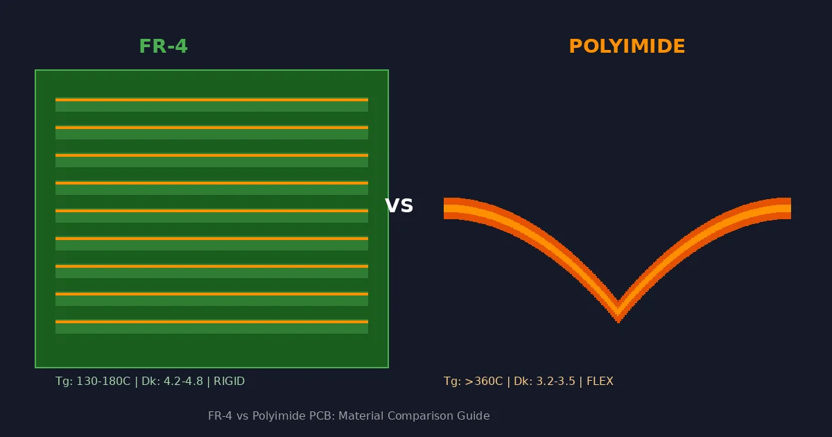
FR-4 and polyimide serve fundamentally different roles in PCB design: FR-4 (epoxy-glass laminate, Tg 130-180C, Dk 4.2-4.8) is the default choice for rigid boards where cost efficiency and mechanical rigidity matter, while polyimide (Tg >360C, continuous use to 250C, Dk 3.2-3.5) is required when the application demands dynamic flexibility (bend cycles >100,000), sustained high-temperature operation above 150C, or the thin profile and weight reduction that only a film-based substrate can provide. The cost premium for polyimide ranges from 2-3x for simple single-layer flex circuits to 5-8x for complex rigid-flex assemblies, making material selection a direct engineering trade-off between performance requirements and budget constraints.
The Core Decision: Why Material Selection Between FR-4 and Polyimide Is Never About Just One Property
Engineers frequently frame the FR-4 versus polyimide decision as a temperature question alone — if the board gets hot, use polyimide; if not, use FR-4. This oversimplification leads to either over-specifying expensive polyimide for applications where high-Tg FR-4 would suffice, or under-specifying FR-4 in applications where mechanical flexibility or chemical resistance eventually causes field failures. The reality is that material selection between these two substrates involves a matrix of interrelated properties, and the correct choice depends on which combination of requirements your application actually imposes.
FR-4 dominates PCB manufacturing for the same reason it has for decades: it offers the best balance of mechanical strength, electrical insulation, processability, and cost across the widest range of applications. Approximately 85-90% of all PCBs manufactured globally use some variant of FR-4 laminate. Polyimide serves the remaining applications where FR-4’s limitations become unacceptable — primarily in dynamic flex circuits, high-temperature environments, and weight-critical aerospace or medical designs where thin-film construction provides advantages that rigid laminates simply cannot match.
From our production floor, the clearest indicator of whether a design needs polyimide is not temperature alone but the combination of operating conditions. A board that runs at 140C continuously but never flexes may work fine on high-Tg FR-4. A board that runs at only 80C but must survive 200,000 flex cycles absolutely requires polyimide. Understanding where your application falls on both axes — thermal and mechanical — is the starting point for a correct material decision.
Material Composition and Structure
FR-4: Epoxy-Glass Laminate
FR-4 is a composite material consisting of woven E-glass fiber cloth impregnated with a brominated epoxy resin system. The glass fiber provides mechanical rigidity and dimensional stability, while the epoxy resin fills the spaces between glass fibers and bonds the laminate layers together. The “FR” designation stands for Flame Retardant, indicating the material meets UL 94 V-0 vertical burn requirements — achieved through the bromine content in the epoxy system (typically 18-21% by weight).
The glass weave pattern (commonly 7628, 2116, or 1080 styles) determines mechanical properties, resin content ratio, and to some degree, dielectric uniformity. Standard FR-4 uses a dicyandiamide (DICY) curing agent with a glass transition temperature of 130-140C. High-Tg variants replace DICY with phenolic or multi-functional epoxy systems, pushing Tg to 170-180C while maintaining processing compatibility with standard fabrication equipment.
The key structural characteristic of FR-4 is rigidity. The glass fiber reinforcement creates a stiff laminate that maintains flatness under thermal stress (up to its Tg), supports component weight without deflection, and provides excellent drilling characteristics. This rigidity is simultaneously its greatest asset for conventional PCB applications and its fundamental limitation for flex applications.
Polyimide: Film-Based Substrate
Polyimide PCB substrates are based on a completely different material architecture. Instead of woven glass reinforcement, polyimide uses a thin polymer film (typically DuPont Kapton or equivalent) that derives its properties entirely from the molecular structure of the polyimide polymer chain. The aromatic ring structure of polyimide creates a material with exceptional thermal stability, chemical resistance, and mechanical flexibility that no epoxy-glass system can approach.
The most common polyimide substrates for flex circuits use film thicknesses of 12.5, 25, 50, or 75 micrometers — dramatically thinner than the 100-200 micrometer cores typical of FR-4 multilayer constructions. Copper foil is bonded directly to the polyimide film using either an acrylic adhesive (adhesive-based construction) or an adhesiveless process (cast polyimide directly on copper). The adhesiveless construction offers superior thermal performance and thinner profiles but costs more to produce.
For rigid polyimide boards (used in high-temperature applications without flex requirements), the substrate uses glass-reinforced polyimide laminates — combining polyimide resin with woven glass similar to FR-4, but replacing the epoxy with polyimide for dramatically higher temperature resistance. These boards are rigid like FR-4 but survive operating temperatures that would destroy any epoxy-based material.
Need Both FR-4 and Polyimide in One Design?
Rigid-flex PCBs combine FR-4 rigid sections with polyimide flex zones in a single integrated assembly. Our engineering team helps optimize the transition zones and stackup for maximum reliability.
Get Rigid-Flex QuoteThermal Performance: The Temperature Ceiling
Glass Transition and Decomposition Temperature
The thermal performance comparison between FR-4 and polyimide is not a single-number comparison — it involves understanding three distinct temperature thresholds that affect material behavior differently.
For FR-4, the glass transition temperature (Tg) marks the point where the epoxy resin transitions from a rigid, glassy state to a soft, rubbery state. Standard FR-4 (Tg 130-140C) begins losing dimensional stability above its Tg — the Z-axis expansion rate increases dramatically (from approximately 50 ppm/C below Tg to 250+ ppm/C above Tg), which stresses plated through-holes and vias. High-Tg FR-4 (Tg 170-180C) pushes this transition higher but does not fundamentally change the material’s behavior above its Tg. The decomposition temperature (Td) for FR-4 is approximately 300-330C — the point where the epoxy begins to chemically decompose. Between Tg and Td, FR-4 softens and expands excessively but does not carbonize.
For polyimide, the Tg exceeds 360C for most grades — so far above typical operating temperatures that it effectively never enters the softened state during normal operation. The decomposition temperature exceeds 500C. This means polyimide maintains its mechanical properties, dimensional stability, and dielectric integrity across the entire range of temperatures that electronics typically encounter, including aggressive lead-free reflow profiles (peak temperatures of 260C) that stress FR-4 boards near their thermal limits.
In our facility, we routinely process polyimide flex circuits through multiple reflow cycles without the barrel cracking or pad lifting failures that can occur with standard FR-4 on repeated thermal excursions. The inherent thermal stability of polyimide provides manufacturing margin that FR-4 cannot match for high-reliability applications requiring multiple rework cycles or extended high-temperature exposure.
Continuous Operating Temperature
The practical continuous operating temperature — the temperature at which a board can operate indefinitely without degradation — is significantly lower than the Tg for both materials:
Standard FR-4: 105-110C continuous (well below Tg to maintain reliability margin). High-Tg FR-4: 130-150C continuous. Polyimide (flex): 200-250C continuous depending on grade. Glass-reinforced polyimide (rigid): 250-280C continuous.
For applications in automotive engine compartments (ambient 125-150C plus self-heating), industrial process control near heating elements, aerospace electronics exposed to aerodynamic heating, or downhole oil and gas instrumentation, the continuous temperature requirement alone often mandates polyimide regardless of flex requirements.
Mechanical Properties: Flexibility and Fatigue Life
Dynamic Flex Endurance
The defining mechanical advantage of polyimide over FR-4 is flex endurance — the ability to survive repeated bending cycles without cracking, delamination, or copper fatigue failure. This property makes polyimide the only viable substrate for dynamic flex applications where the circuit bends during normal device operation (printer heads, laptop hinges, disk drive actuators, foldable displays).
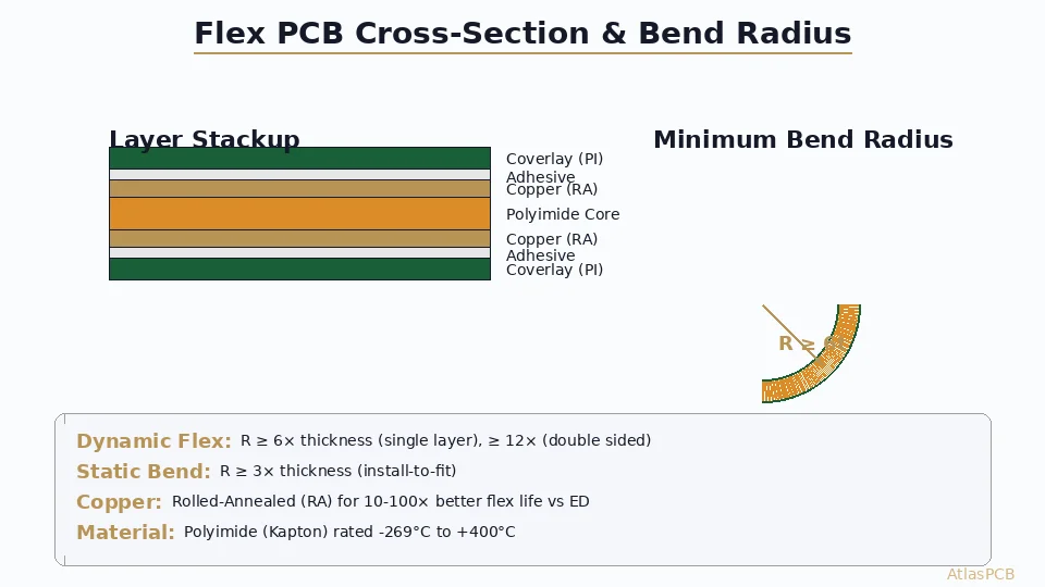
Polyimide flex circuits can withstand 100,000 to over 1,000,000 bend cycles depending on the circuit construction, bend radius, copper thickness, and number of layers. The polyimide film itself has essentially unlimited flex life at reasonable bend radii — the limiting factor is typically copper fatigue, which depends on copper type (rolled annealed copper survives far more cycles than electrodeposited copper), copper thickness (thinner is better for flex), and the ratio of bend radius to total circuit thickness.
FR-4, by contrast, will crack within a single digit number of bend cycles at any meaningful deflection. The glass fiber reinforcement that provides rigidity also makes the material brittle under bending loads. Even thin FR-4 (0.2 mm) can tolerate only a single gentle bend during installation — it cannot survive repeated flexing.
For designs where the circuit must flex during manufacturing or installation but remains static in operation (flex-to-install applications), thin FR-4 may technically work if the bend radius exceeds 10x the board thickness. However, polyimide is still recommended for these applications because it provides margin against the inevitable handling damage and vibration-induced movement that occurs over the product lifetime.
Dimensional Stability and CTE
FR-4 offers excellent in-plane dimensional stability due to its glass fiber reinforcement — X-Y expansion coefficients of approximately 14-17 ppm/C match reasonably well with copper (17 ppm/C), minimizing thermomechanical stress on solder joints during thermal cycling. The Z-axis expansion is higher (50-70 ppm/C below Tg) due to the unreinforced resin between glass layers.
Polyimide film without glass reinforcement has a CTE of approximately 20-30 ppm/C in-plane — slightly higher than FR-4 but still reasonably matched to copper. However, adhesiveless polyimide constructions can achieve CTE values as low as 12-16 ppm/C through controlled molecular orientation during film casting, providing even better copper compatibility than standard FR-4.
High-Temperature or Flex PCB Design Review
Upload your design files and our materials engineering team will recommend the optimal substrate — standard FR-4, high-Tg FR-4, polyimide flex, or rigid-flex — based on your specific operating conditions.
Get Material RecommendationElectrical Properties Comparison
Dielectric Constant and Loss Tangent
The electrical properties of PCB substrates affect signal propagation speed, characteristic impedance, and signal loss. Both FR-4 and polyimide are adequate for most digital applications, but their characteristics diverge at higher frequencies.
FR-4 has a dielectric constant of 4.2-4.8 at 1 GHz (the range reflects variation in glass-to-resin ratio between different laminate styles and manufacturers). The loss tangent (Df) is 0.015-0.020, which produces acceptable insertion loss for signals below approximately 5 GHz. Above 10 GHz, the loss becomes significant enough to limit practical trace lengths.
Polyimide has a dielectric constant of 3.2-3.5 at 1 GHz with a loss tangent of 0.008-0.015 depending on grade. The lower Dk provides approximately 15% faster signal propagation for a given geometry, and the lower Df reduces insertion loss by 2-3 dB per inch at 10 GHz compared to standard FR-4. For high-speed flex interconnects (such as those connecting processing chips to memory in mobile devices), polyimide’s electrical properties are superior to FR-4.
However, for applications above 20 GHz, neither material is optimal. Low-loss hydrocarbon laminates (Megtron 6/7), PTFE (Rogers, Taconic), or LCP (liquid crystal polymer) substrates provide substantially better performance at millimeter-wave frequencies. The FR-4 versus polyimide decision rarely hinges on electrical properties alone — temperature and flexibility requirements dominate the selection.
Moisture Absorption and Insulation Resistance
Polyimide has one notable weakness: higher moisture absorption (approximately 2.5-3.0% by weight) compared to FR-4 (0.10-0.15%). This absorbed moisture can reduce insulation resistance, increase dielectric loss, and cause blistering during high-temperature processing if the material is not properly baked before soldering. In our production line, all polyimide materials are baked at 120C for 2-4 hours before lamination or reflow to drive out absorbed moisture.
FR-4’s low moisture absorption makes it more forgiving in storage and handling — boards can sit on shelves for weeks without requiring pre-bake before assembly. This practical advantage reduces manufacturing complexity and handling costs for high-volume production.
Cost Comparison and Economic Decision Framework
Raw Material and Processing Cost Multipliers
The cost difference between FR-4 and polyimide varies significantly by construction type. Understanding these multipliers helps engineers make informed trade-off decisions:
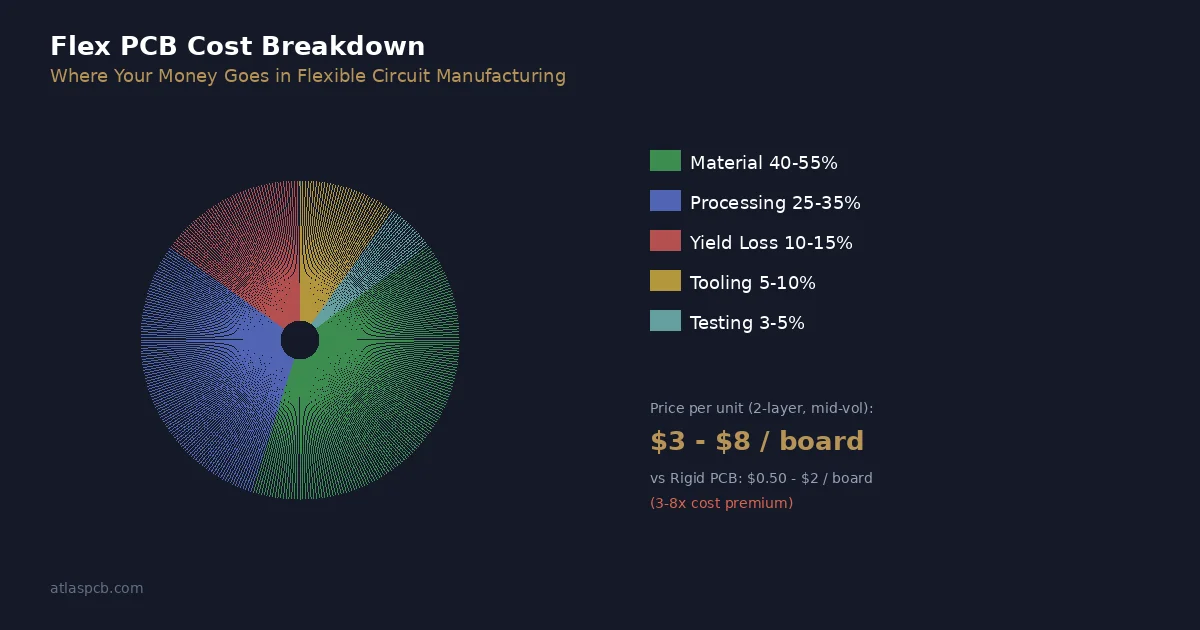
Simple 2-layer rigid board: FR-4 is baseline (1.0x). Equivalent 2-layer rigid polyimide board: approximately 1.5-2.0x (material cost higher, processing similar). Single-layer flex circuit: 2.0-3.0x baseline FR-4 rigid equivalent area. Multi-layer flex (2-4 layers): 3.0-5.0x. Rigid-flex (FR-4 rigid zones + polyimide flex zones): 5.0-8.0x.
The cost increase for rigid-flex is not simply additive — the manufacturing process involves sequential lamination, controlled-depth milling to expose flex zones, coverlay application, and extensive handling precautions for the thin flex portions. Each step adds process cost, yield loss, and quality control complexity.
Total System Cost Analysis
Despite higher per-board cost, polyimide can reduce total system cost in applications where it replaces multi-board assemblies connected by wire harnesses or cables. A single rigid-flex assembly that replaces three rigid boards, two flex cables, and six board-to-board connectors may cost more as a bare board but delivers lower total system cost when you account for eliminated connector costs, reduced assembly labor, improved reliability (fewer solder joints), and smaller overall volume.
Our engineering team routinely helps customers evaluate this trade-off. The break-even point depends on production volume, connector costs, assembly labor rates, and reliability requirements. For volumes below 1,000 units, the engineering and tooling costs of rigid-flex may not amortize — separate rigid boards with flex cables often make more economic sense. Above 5,000 units, rigid-flex typically wins on total cost.
Compare FR-4 and Polyimide Pricing for Your Design
Upload your Gerber files and we will quote both FR-4 rigid and polyimide flex/rigid-flex options, with cost breakdown showing where the premium goes and whether rigid-flex saves total system cost.
Get Comparative QuoteDecision Framework: When to Choose Each Material
Choose FR-4 When:
The application operates below 130C continuously (standard) or below 150C (high-Tg). The board remains static throughout its operational lifetime — no repeated bending or flexing required. Cost is a primary concern and the design does not benefit from flex integration. The operating environment does not expose the board to aggressive chemicals or sustained high humidity. Standard mechanical rigidity is required to support heavy components or withstand vibration without board-level flexure.
Choose Polyimide When:
The circuit must flex repeatedly during operation (dynamic flex: laptop hinges, printer mechanisms, robotic joints, foldable devices). Operating temperature exceeds 150C continuously or involves repeated excursions above 200C. The application requires thin, lightweight construction where rigid boards would add unacceptable mass or volume. Chemical exposure demands a substrate resistant to solvents, fuels, or hydraulic fluids that would degrade FR-4 epoxy. The design integrates multiple rigid sections with flex interconnects (rigid-flex), eliminating connectors and cables for improved reliability.
The Gray Zone: High-Tg FR-4 vs Rigid Polyimide
For rigid boards operating in the 130-180C range without flex requirements, the decision between high-Tg FR-4 and glass-reinforced rigid polyimide depends on:
Reliability requirements: If the board must survive 1000+ thermal cycles between room temperature and operating temperature without degradation, rigid polyimide provides superior fatigue resistance. For fewer cycles or less extreme temperature ranges, high-Tg FR-4 is sufficient.
Moisture sensitivity: If the environment is humid and the board cannot be easily baked before assembly, FR-4’s lower moisture absorption makes it more forgiving.
Lead-free processing margin: If the assembly requires multiple reflow passes (double-sided surface mount with rework), polyimide’s higher Td provides significantly more process margin than even high-Tg FR-4.
Cost tolerance: High-Tg FR-4 costs approximately 10-20% more than standard FR-4. Rigid polyimide costs 50-100% more. If the application succeeds with high-Tg FR-4, the cost savings are substantial.
Manufacturing Considerations from Our Production Floor
Processing Differences That Affect Lead Time
In our facility, FR-4 boards follow standard multilayer processing with well-established parameters — drilling speeds, plating chemistry, imaging resolution, and etching rates are all optimized for epoxy-glass substrates. Lead times for standard FR-4 multilayer boards are typically 5-8 days for 4-6 layer constructions.
Polyimide flex and rigid-flex boards require specialized handling throughout the process. The thin, flexible nature of polyimide panels means they cannot be processed on the same automated equipment without fixturing modifications. Drilling polyimide requires different spindle speeds and feed rates (polyimide is more abrasive than FR-4 epoxy, causing faster drill wear). Coverlay lamination — the flex circuit equivalent of solder mask — involves a separate pressing cycle with different temperature and pressure profiles. These additional steps typically add 3-5 days to lead time compared to equivalent-complexity FR-4 boards.
Design for Manufacturing Differences
Several DFM rules differ between FR-4 and polyimide substrates that designers must account for:
Minimum bend radius for dynamic flex: 6x the total flex circuit thickness for single-layer, 12x for multi-layer. Placing components or vias within the bend zone is prohibited.
Stiffener requirements: Flex circuits often need FR-4 or polyimide stiffeners bonded to component mounting areas to provide rigidity for SMT assembly. The stiffener adds thickness and must be accounted for in the overall assembly clearance.
Copper type specification: For dynamic flex, rolled annealed (RA) copper must be specified — electrodeposited (ED) copper has insufficient fatigue resistance. RA copper also requires routing traces perpendicular to the rolling direction (grain direction) for maximum flex endurance.
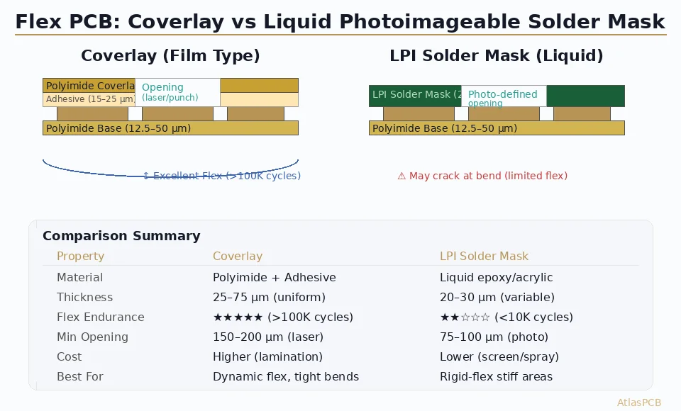
Coverlay versus photoimageable solder mask: Flex circuits typically use a polyimide coverlay (adhered film) rather than liquid photoimageable solder mask. Coverlay openings have minimum dimensions of approximately 0.2 mm due to the mechanical registration of the film, compared to 0.05-0.10 mm achievable with LPSM.
Ready to Choose Your Substrate?
Whether your design needs standard FR-4, high-Tg FR-4, polyimide flex, or rigid-flex construction, our engineering team provides material recommendations based on your specific operating conditions, mechanical requirements, and budget constraints.
Upload Design for Material ReviewReviewed by AtlasPCB Engineering Team
This comparison reflects material parameters and manufacturing experience from our FR-4, flex, and rigid-flex production lines. Specific grades and capabilities vary by manufacturer — contact our engineering team for material recommendations based on your application’s operating profile, mechanical requirements, and reliability targets.
About AtlasPCB — We specialize in complex PCB manufacturing for HDI, RF, and high-reliability applications. Explore our rigid-flex PCB manufacturing . Every order includes free engineering review. Get your quote.
Reviewed by AtlasPCB Engineering Team — IPC-certified manufacturing specialists with 15+ years of production experience in HDI, RF, and high-reliability PCB fabrication. Content based on factory floor data and real customer design reviews.
Frequently Asked Questions
At what temperature should I switch from FR-4 to polyimide?
Is polyimide always more expensive than FR-4?
Can I use FR-4 for a flex circuit?
What is the dielectric constant difference and does it matter?
- FR-4
- polyimide
- PCB materials
- flex PCB
- high temperature PCB
- material selection
- rigid-flex