· AtlasPCB Engineering · Engineering · 6 min read
EV Battery Management PCB: Rigid-Flex Design and Manufacturing Requirements for 800V BMS
Engineering guide for PCB design and manufacturing of 800V EV battery management systems. Covers rigid-flex construction for cell-to-module connections, creepage distance requirements at high voltage, thermal management of balancing circuits, and IPC/automotive qualification requirements for BMS PCBs.
Why 800V BMS Demands Specialized PCB Manufacturing
The transition from 400V to 800V battery architectures (Porsche Taycan, Hyundai E-GMP, GM Ultium) fundamentally changes PCB manufacturing requirements for battery management systems. At 800V working voltage, the clearance and creepage distances required by safety standards (IEC 60664-1, UL 840) create physical constraints that standard PCB design tools and fabricators are not equipped to handle.
A typical 800V BMS must monitor 96-108 series cells (3.7V nominal each), distributed across 6-12 physical modules in the battery pack. The PCB interconnects must:
- Survive 15+ years in automotive environment (-40°C to +85°C ambient)
- Withstand continuous vibration (IEC 60068-2-6: 10-500 Hz, 50 m/s²)
- Maintain 4-6mm isolation between HV and LV circuits at every point
- Connect cell balancing circuits across physically separated modules
- Meet ASIL-D functional safety requirements per ISO 26262
Rigid-flex PCB construction is the dominant architecture because it satisfies all requirements with minimum connector count — directly improving MTBF and simplifying FMEA analysis.
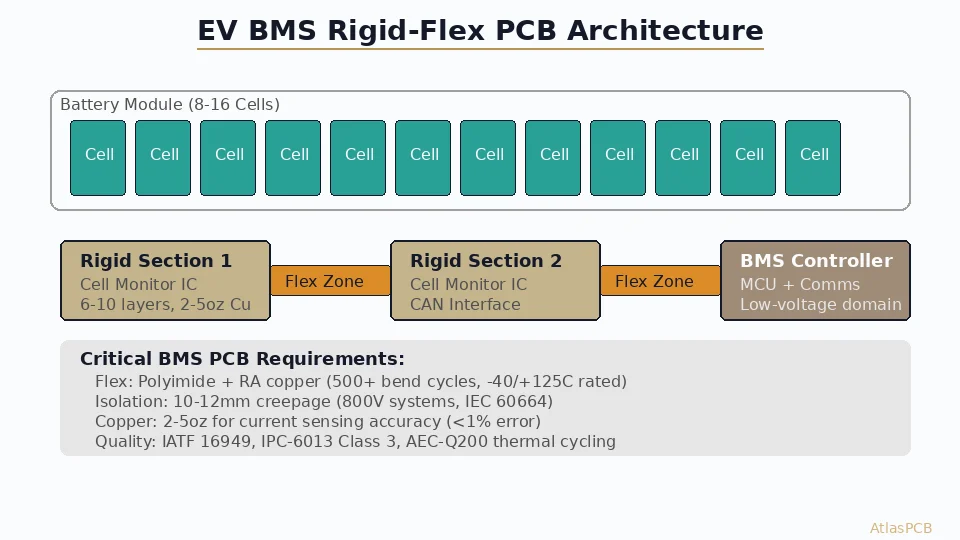
Rigid-Flex Architecture for 800V BMS
Typical Configuration
| Section | Construction | Function | Layers |
|---|---|---|---|
| Main controller (rigid) | 8-10 layer HDI | BMS IC, MCU, CAN/LIN interface | L1-L8/10 |
| Cell monitoring (rigid) | 4-6 layer standard | AFE IC, balancing MOSFETs, filtering | L1-L4/6 |
| Module interconnect (flex) | 2-layer flex | HV cell sense lines between modules | 2L polyimide |
| HV sense input (rigid) | 4-layer | Current sense, isolation barrier | L1-L4 |
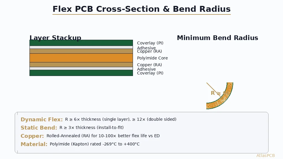
Flex Section Design
The flex sections carry cell voltage sense lines (low current, <10mA) between physically separated battery modules. Key specifications:
- Conductor: 0.5-1oz copper on adhesiveless polyimide (for dynamic flex capability)
- Bend radius: Minimum 6:1 (flex thickness x 6) for static installation bends
- Vibration survivability: Must pass IEC 60068-2-6 endurance testing (10 million cycles at 20-30Hz)
- Temperature rating: Polyimide film rated to 200°C (exceeds automotive 150°C requirement)
The flex must maintain creepage distance between adjacent cell sense lines. At 4.2V per cell potential difference, this is trivial — but the cumulative potential from cell 1 to cell 96 is 800V+ and requires full isolation management at the flex-to-rigid transitions.
⚡ Building 800V BMS? Start Here.
AtlasPCB manufactures rigid-flex assemblies for automotive BMS applications with full IATF 16949 process compliance and IPC-6013 Class 3 qualification. Our engineering team reviews your isolation gap requirements and flex reliability specifications before quoting. Discuss your BMS PCB requirements →
High-Voltage Isolation: PCB Layout Constraints
Creepage and Clearance Requirements
For 800V working voltage in a sealed automotive environment (pollution degree 2, material group IIIa/IIIb for FR-4):
| Standard | Creepage (min) | Clearance (min) | Application |
|---|---|---|---|
| IEC 60664-1 | 4.0 mm | 3.2 mm | Basic insulation |
| UL 840 | 4.8 mm | 3.6 mm | Reinforced insulation |
| OEM typical spec | 5.0-6.0 mm | 4.0-5.0 mm | Design target with margin |
PCB design implication: The 5-6mm isolation gap between HV and LV domains cannot be violated on ANY layer — including internal routing layers. This creates dead zones on the PCB that reduce routing density significantly.
Slot Isolation Technique
For maximizing creepage in limited board area, routed slots through the PCB substrate increase surface path length. A 1.0mm wide slot with 2.5mm length on each side effectively doubles the creepage distance in a given board area:
- Without slot: 5mm board gap → 5mm creepage
- With slot: 3mm board gap + 2.5mm slot wall + 2.5mm slot wall → 8mm effective creepage
This technique is standard in BMS design and requires the fabricator to route precise slots with +/-0.1mm tolerance and clean slot walls (no debris that could reduce effective creepage).
Internal Layer Keep-Out
Every internal layer must respect the HV isolation boundary. This is the most common DFM error in BMS designs — designers maintain proper clearance on outer layers but allow inner-layer routing to cross the isolation boundary. In our DFM review, we verify EVERY layer for isolation compliance and flag any violations before fabrication.
Thermal Management for Balancing Circuits
Cell balancing (passive dissipative type) generates significant heat — a 100mAh balance current at 4.2V dissipates 420mW per channel. With 12-16 channels on a single monitoring IC, total dissipation reaches 5-7W per module board.
PCB thermal strategies:
- Heavy copper on internal power layers (2oz minimum for thermal spreading)
- Thermal via arrays (0.3mm diameter, 1.0mm pitch) under balancing MOSFETs
- Exposed copper heat-sink pads on bottom layer with thermal paste to module housing
- Copper coin inserts for highest-dissipation components (optional, adds $5-10/board)
Manufacturing and Qualification Requirements
IPC-6013 Class 3 Compliance
| Requirement | Class 2 (standard) | Class 3 (BMS required) |
|---|---|---|
| Annular ring (internal) | 50μm minimum | 75μm minimum |
| Conductor width tolerance | +/-20% | +/-10% |
| Flex copper adhesion | 0.7 N/mm | 1.0 N/mm |
| IST testing | Not required | Required per lot |
| Microsection | Sample basis | Per lot, per build |
| Ionic cleanliness | <1.56μg/cm² NaCl eq. | <0.75μg/cm² NaCl eq. |
Automotive-Specific Testing
Beyond IPC requirements, automotive OEMs typically require:
- Hipot testing: 2 x Vworking + 1000V = 2600V DC applied between HV and LV domains for 60 seconds. 100% of boards must pass with leakage current < 1mA.
- Thermal cycling: -40°C to +125°C, 1000 cycles (per AEC-Q100 Grade 1 equivalent)
- Vibration endurance: IEC 60068-2-6, 10-500 Hz sweep at 50 m/s², 8 hours per axis
- Humidity exposure: 85°C/85% RH for 1000 hours with hipot retest after conditioning
🏭 IATF 16949 Qualified Rigid-Flex Manufacturing
AtlasPCB operates IATF 16949 certified production lines for automotive rigid-flex PCBs. We support prototype through mass production with full PPAP documentation, IST qualification, and hipot testing capability to 5000V. Explore automotive PCB capabilities →
Material Selection for BMS Rigid-Flex
| Component | Recommended Material | Why |
|---|---|---|
| Rigid sections | FR-4 Tg170+, CTI 600V | High CTI for creepage compliance |
| Flex sections | Adhesiveless polyimide (DuPont AP) | Better flex life, higher temperature rating |
| Coverlay | 1-mil polyimide + 1-mil adhesive | Standard for automotive flex |
| Stiffeners | FR-4 or stainless steel | Component mounting support |
| Bonding | Acrylic or epoxy adhesive | Temperature range compatibility |
| Surface finish | ENIG (components) | Lead-free assembly, flat surface |
Critical material note: Standard FR-4 has a Comparative Tracking Index (CTI) of 175-250V. At 800V working voltage, this is insufficient — the board surface could track (carbonize) at the isolation gap. Specify high-CTI material (CTI ≥ 600V per IEC 60112) for all rigid layers in the HV section. Materials like Isola 370HR or Panasonic R-1755V meet this requirement.
Design for Manufacturability — BMS Specific
- Slot tolerance: Specify +/-0.1mm on isolation slots (not standard +/-0.15mm)
- Flex transition zone: Allow minimum 3mm transition length from rigid to flex
- Coverlay registration: Design coverlay openings 2mil larger than pad on each side
- Panel separation: Use tab routing (not V-score) to avoid flex damage during depaneling
- Marking requirements: Permanent laser marking for traceability (inkjet fades in automotive thermal cycling)
- Ionic contamination: Specify cleaning to <0.75μg/cm² (tighter than standard 1.56μg/cm²)
Summary
800V BMS PCBs represent one of the most demanding applications for rigid-flex manufacturing — combining high-voltage isolation requirements, automotive environmental qualification, Class 3 reliability standards, and the inherent manufacturing complexity of rigid-flex construction. Success requires a fabrication partner with genuine automotive process qualification and engineering expertise in high-voltage PCB design.
🔋 Ready to Develop Your BMS PCB?
From prototype through PPAP, AtlasPCB supports the full automotive BMS development cycle. Our engineering team provides DFM review, stackup optimization, and material recommendations specific to high-voltage rigid-flex applications. Start your BMS PCB project →
Related Reading
About AtlasPCB — We specialize in complex PCB manufacturing for HDI, RF, and high-reliability applications. Explore our rigid-flex PCB manufacturing . Every order includes free engineering review. Get your quote.
Reviewed by AtlasPCB Engineering Team — IPC-certified manufacturing specialists with 15+ years of production experience in HDI, RF, and high-reliability PCB fabrication. Content based on factory floor data and real customer design reviews.
- EV BMS PCB
- rigid-flex
- 800V battery management
- automotive PCB
- high voltage PCB
- electric vehicle