· Atlas PCB Engineering Team · Engineering · 23 min read
4-Layer PCB Stackup Design: Configurations, Materials, and Impedance Control from a Manufacturer's Perspective
A manufacturer's guide to 4-layer PCB stackup design covering the three standard configurations (S-G-P-S, S-G-G-S, G-S-S-G), real prepreg and core material specifications, worked impedance calculations, cost implications of standard vs custom stackups, and a ready-to-use fab drawing specification template.
Quick Answer
A 4-layer PCB stackup consists of two outer signal layers and two inner plane layers separated by prepreg and core dielectrics. The three standard configurations are Signal-Ground-Power-Signal (best general-purpose balance), Signal-Ground-Ground-Signal (superior EMI performance for high-speed designs), and Ground-Signal-Signal-Ground (maximum shielding for RF applications). The standard 1.6mm build uses a 1.2mm FR-4 core between the inner layers with 0.2mm 2116 prepreg on each side, achieving 50-ohm single-ended impedance with approximately 0.27mm trace width. Using your manufacturer's standard stackup saves 15-25% versus custom builds and reduces lead time by 2-3 days.
What Makes a 4-Layer Stackup Work — The Manufacturer’s View
Every 4-layer PCB that arrives at our lamination press tells a story about the engineer who designed it. Some stackups are meticulously specified with exact dielectric thicknesses and material callouts; others arrive with nothing more than “4 layers, 1.6mm, FR-4” and leave every critical decision to the manufacturer. Both approaches can produce functional boards, but the difference in performance predictability is substantial.
A 4-layer PCB stackup is fundamentally a sandwich structure: two outer copper layers carrying signal traces and component pads, two inner copper layers serving as reference planes, and three dielectric layers holding everything together. The inner layers typically occupy dedicated ground and power plane roles, though alternative configurations exist for specialized applications. What transforms this simple description into a precise engineering specification is the detail — which materials fill those dielectric gaps, how thick each layer actually is after pressing, and what electromagnetic environment that geometry creates for your signals.
From a manufacturing perspective, the 4-layer board represents the entry point into true multilayer fabrication. Unlike 2-layer boards that are simply double-sided copper-clad laminates with through-hole connections, a 4-layer board requires a lamination press cycle where inner layer patterns are aligned, sandwiched between prepreg sheets, and bonded under heat and pressure into a monolithic structure. This process fundamentally changes what the board can do electrically — continuous copper planes provide low-impedance return paths, predictable transmission line geometry enables controlled impedance, and the shielding effect of sandwich construction dramatically reduces electromagnetic interference.
The construction sequence matters for understanding how your design choices translate into physical reality. We start with a double-sided copper-clad core — typically 1.0 to 1.2mm of FR-4 with 35-micrometer copper on both faces. The inner layer circuitry (your ground and power planes) is patterned on this core through standard photolithography and etching. Once inspected, this patterned core is placed between sheets of prepreg — partially cured fiberglass cloth impregnated with epoxy resin — with outer copper foils on top and bottom. The entire assembly enters a hydraulic press at approximately 175 degrees Celsius and 300 PSI for 60 to 90 minutes. The prepreg resin flows, fills gaps around inner layer features, and cures into solid dielectric, permanently bonding all layers into the finished multilayer laminate.
Need a 4-Layer PCB Quote?
Upload your Gerber files for a free DFM review. Our engineers verify your stackup specification and provide impedance modeling before production.
Get Your QuoteThe Three Standard 4-Layer Configurations
Three fundamental layer arrangements account for over 95 percent of the 4-layer boards we manufacture. Each serves a distinct electrical purpose, and choosing between them is the single most consequential decision in your stackup design. The differences are not academic — they directly determine your signal integrity performance, EMI radiation profile, and manufacturing cost.
Configuration 1: Signal-Ground-Power-Signal (S-G-P-S)
This is the workhorse configuration that handles the majority of commercial electronics. Both outer layers carry signal traces and component pads, Layer 2 serves as a continuous ground plane, and Layer 3 provides power distribution.
The electrical logic behind this arrangement is straightforward. Top-layer signals see a solid ground plane immediately beneath them at a spacing of 0.15 to 0.20mm (one prepreg thickness). This tight coupling to a reference plane creates well-defined microstrip transmission lines with predictable characteristic impedance. Bottom-layer signals reference the power plane, which also provides an acceptable return path for frequencies below approximately 100 MHz where the power plane’s decoupling capacitors maintain low impedance.
In our production statistics, S-G-P-S accounts for roughly 60 percent of 4-layer orders. It works reliably for microcontroller-based designs, USB 2.0 interfaces, SPI and I2C buses, moderate-speed Ethernet (10/100 Mbps), industrial control systems, and consumer IoT products. The configuration starts struggling only when differential signaling speeds exceed 1 Gbps or when bottom-layer traces carry signals sensitive to the impedance discontinuities that power plane splits can create.
One practical advantage from the manufacturing side: this configuration allows your power plane to be split into multiple voltage domains (3.3V, 1.8V, 5V regions) without compromising top-layer signal integrity, because the top signals reference the undisturbed ground plane rather than the segmented power layer below it.
Configuration 2: Signal-Ground-Ground-Signal (S-G-G-S)
When signal integrity and EMI performance take priority over convenient power distribution, the dual-ground configuration delivers measurably superior results. Both inner layers serve as ground planes, creating a symmetrical shielding structure around the entire board cross-section.
The electromagnetic benefit is substantial. Every signal trace on both outer layers now references a solid, continuous ground plane at the closest possible spacing. There are no power plane splits to disrupt return current paths, no impedance discontinuities where traces cross between voltage domains. The result is lower radiated emissions, better signal integrity margins, and more predictable impedance control across the entire board surface.
The trade-off is power distribution. Without a dedicated power plane, supply current must flow through copper pours, wide traces, or partial planes on the signal layers themselves. This is entirely manageable for designs with moderate power requirements — a typical STM32 microcontroller system drawing under 500 mA total can be powered comfortably through 0.5mm traces and local copper fills. However, designs with multiple high-current power rails or extensive analog circuitry requiring clean power planes may find this approach limiting.
We recommend S-G-G-S for USB 3.0 and higher, HDMI interfaces, designs requiring FCC Class B certification with minimal margin, differential pairs running above 1 GHz, and any application where the bottom layer carries signals as critical as the top layer. The dual ground planes ensure both signal layers have identical electromagnetic environments, which eliminates the asymmetric performance that S-G-P-S can exhibit between top and bottom routing.
Configuration 3: Ground-Signal-Signal-Ground (G-S-S-G)
The least common of the three standard configurations places ground planes on both outer surfaces and routes signals exclusively on the inner layers. This creates a fully shielded stripline environment where electromagnetic fields from the signal traces are completely contained between the ground planes.
From an EMI perspective, this is the gold standard for a 4-layer board. External radiation approaches zero because the outer ground planes form a continuous Faraday cage. The board also becomes highly immune to external electromagnetic interference, making it suitable for sensitive measurement equipment and designs operating in noisy industrial environments.
The practical constraints, however, are significant. With signals on inner layers, component-to-trace connections require vias for nearly every pad — dramatically increasing via count, complicating routing, and consuming board space with via antipad clearances in the ground planes. Power must also be distributed on the signal layers or through the outer ground planes with appropriate isolation. For these reasons, G-S-S-G is typically reserved for RF receiver front-ends, precision analog measurement circuits, and military/aerospace applications where shielding requirements justify the routing complexity penalty.
Real Material Specifications — What Your Fab Actually Uses
This section addresses something most stackup guides skip entirely: the actual materials that constitute your dielectric layers. Knowing that you have “0.2mm of prepreg” between layers tells you the geometry, but it does not tell you the dielectric constant, loss tangent, glass transition temperature, or mechanical properties of that material. These details directly affect impedance accuracy, insertion loss at high frequencies, and thermal reliability.
Prepreg Types and Their Properties
Prepreg (pre-impregnated fiberglass) comes in standardized glass cloth styles designated by numbers that indicate the weave pattern and glass content. For 4-layer PCBs in standard FR-4, four prepreg styles dominate production:
106 prepreg uses the thinnest glass cloth with the highest resin content (approximately 70 percent resin by weight). Nominal cured thickness is 0.05mm per ply. Its high resin content provides excellent flow for filling around inner layer features, but the thin glass cloth offers less dimensional stability and more variable dielectric constant (typically 3.9 to 4.2 depending on resin content variation). We use 106 primarily in thin-board builds where total thickness must stay below 0.8mm.
1080 prepreg represents the most common thin prepreg in production use. Each ply cures to approximately 0.075mm with a resin content around 62 percent. The slightly heavier glass cloth compared to 106 provides better Dk consistency (typically 4.0 to 4.3) while still offering good resin flow. This is our default choice for 1.0mm total-thickness 4-layer builds.
2116 prepreg is the standard workhorse for most 4-layer PCBs. Cured thickness is approximately 0.12mm per ply with resin content around 52 percent. The balanced glass-to-resin ratio provides consistent dielectric properties (Dk 4.2 to 4.5 at 1 MHz, approximately 4.1 to 4.3 at 1 GHz) and good mechanical strength. For a standard 1.6mm board, we typically use one or two plies of 2116 between the outer copper foils and inner plane layers.
7628 prepreg is the thickest standard style at approximately 0.18mm per ply cured. Its high glass content (approximately 58 percent) yields the most stable Dk values (4.5 to 4.7 at 1 MHz) but the lowest resin availability for flow. We use 7628 when thicker dielectric spacing is needed without stacking multiple plies, or when maximum Z-axis mechanical stability is the priority.
Core Materials
The core — the inner laminate that carries your ground and power plane patterns — is a fully cured FR-4 panel with copper on both sides. Standard core thicknesses for 4-layer builds range from 0.4mm to 1.2mm, with 1.0mm and 1.2mm being the most common for standard 1.6mm finished boards.
For standard-Tg applications (Tg 135-140 degrees Celsius), we typically stock Shengyi S1141 or equivalent from ITEQ (IT-140). For mid-Tg builds (Tg 150-155 degrees Celsius), Shengyi S1150G or ITEQ IT-150GS provides enhanced thermal reliability for lead-free assembly processes. High-Tg requirements (Tg 170+ degrees Celsius) call for Shengyi S1170 or ITEQ IT-180A, which are common for automotive and industrial applications exposed to elevated operating temperatures.
The dielectric constant of your core material affects impedance on the bottom signal layer (which references the inner ground plane through the core thickness in S-G-P-S configuration). Most standard FR-4 cores measure Dk 4.3 to 4.6 at 1 MHz, dropping to approximately 4.1 to 4.3 at 1 GHz due to the frequency-dependent nature of epoxy resin polarization.
Standard 1.6mm Stackup — Material Breakdown
To make this concrete, here is the exact material composition of our most frequently produced 4-layer stackup:
| Layer | Material | Thickness | Dk at 1 GHz |
|---|---|---|---|
| Solder mask (top) | Taiyo PSR-2000 | 0.015mm | - |
| Copper L1 (signal) | Electrodeposited Cu | 0.035mm (1 oz) | - |
| Prepreg | Shengyi S1141 2116 x1 ply | 0.12mm | 4.25 |
| Copper L2 (ground) | Electrodeposited Cu | 0.035mm (1 oz) | - |
| Core | Shengyi S1141 | 1.00mm | 4.30 |
| Copper L3 (power) | Electrodeposited Cu | 0.035mm (1 oz) | - |
| Prepreg | Shengyi S1141 2116 x1 ply | 0.12mm | 4.25 |
| Copper L4 (signal) | Electrodeposited Cu | 0.035mm (1 oz) | - |
| Solder mask (bottom) | Taiyo PSR-2000 | 0.015mm | - |
Total finished thickness: approximately 1.57mm (within the standard 1.6mm tolerance of plus or minus 10 percent per IPC-6012)
This stackup produces the following nominal impedance values before copper plating adds thickness to the outer layers: 50-ohm single-ended microstrip at approximately 0.27mm (10.6 mil) trace width on L1 referencing the L2 ground plane through 0.12mm of 2116 prepreg.
Impedance Control — Worked Calculations for Common Targets
One area where published stackup guides consistently fall short is providing actual impedance calculations with real numbers. Engineers need to know what trace width achieves their target impedance on a specific stackup, and that answer depends on the actual dielectric thickness and constant — not abstract formulas.
50-Ohm Single-Ended Microstrip (L1 to L2 Reference)
For our standard 1.6mm stackup with a single ply of 2116 prepreg (0.12mm dielectric, Dk 4.25 at signal frequency):
Using the IPC-2141 microstrip impedance formula with corrections for solder mask:
- Dielectric height (h): 0.12mm (4.72 mil)
- Trace thickness (t): 0.035mm (1.38 mil) base copper plus approximately 0.025mm plating = 0.060mm total
- Effective Dk accounting for solder mask: approximately 3.9 (weighted average of FR-4 below and solder mask above)
- Target impedance: 50 ohms
Result: trace width approximately 0.27mm (10.6 mil) for 50-ohm characteristic impedance.
This is comfortably above the minimum trace width capability for standard etching processes (typically 0.10mm or 4 mil), meaning 50-ohm impedance on this stackup imposes no manufacturing difficulty or cost premium for the trace geometry itself.
100-Ohm Differential Pair (L1 to L2 Reference)
For edge-coupled differential microstrip on the same stackup:
- Same dielectric parameters as above
- Individual trace width: 0.15mm (5.9 mil)
- Edge-to-edge spacing: 0.18mm (7.1 mil)
- Differential impedance: approximately 100 ohms
These dimensions are achievable with standard photolithography and etching processes. The spacing is the critical parameter — tighter spacing reduces differential impedance while wider spacing increases it. Our standard process capability maintains plus or minus 0.025mm on trace width and spacing, which translates to approximately plus or minus 8 percent impedance variation — within the standard plus or minus 10 percent tolerance specification.
What Changes If You Use a Different Prepreg
The choice of prepreg directly scales trace width for a given impedance target. Here is how the three common prepreg options compare for 50-ohm single-ended microstrip:
| Prepreg Style | Dielectric Thickness | Dk at 1 GHz | Trace Width for 50 Ohm |
|---|---|---|---|
| 1080 (1 ply) | 0.075mm | 4.20 | 0.165mm (6.5 mil) |
| 2116 (1 ply) | 0.12mm | 4.25 | 0.27mm (10.6 mil) |
| 7628 (1 ply) | 0.18mm | 4.50 | 0.35mm (13.8 mil) |
| 2116 (2 ply) | 0.24mm | 4.25 | 0.52mm (20.5 mil) |
Notice the relationship: thinner dielectric requires narrower traces, which may approach manufacturing limits and certainly limits current-carrying capacity. Thicker dielectric requires wider traces, consuming more routing space. The 2116 single-ply option sits in the comfortable middle ground where trace widths are neither too narrow for reliable etching nor too wide for reasonable routing density.
Custom Stackup Design Assistance
Our engineers can model impedance for your specific stackup configuration and provide optimized trace width recommendations before you finalize routing.
Request Stackup ReviewStandard vs Custom Stackups — The Cost and Lead Time Reality
One of the most consequential decisions in 4-layer PCB procurement is whether your design can use a manufacturer’s standard stackup or requires a custom configuration. This choice directly affects both your unit cost and delivery timeline in ways that many engineers do not anticipate until they receive their first quote.
What “Standard Stackup” Means in Practice
Every PCB manufacturer maintains a library of pre-qualified stackup configurations that they produce routinely. These standard builds use materials already in stock (eliminating procurement delays), have established lamination press recipes (eliminating process development time), and carry verified impedance characterization data (eliminating test coupon development costs). For our facility, the standard 4-layer builds include 1.0mm, 1.2mm, and 1.6mm total thickness options in both standard-Tg and mid-Tg FR-4, with pre-characterized impedance data for common trace geometries.
When you specify a standard stackup, your boards enter production immediately without engineering hold. The impedance model is already validated against test coupons from previous production runs, so we can guarantee your impedance specification without additional coupon fabrication charges. Material is in stock and cut to panel size, ready for inner layer imaging.
What Triggers a “Custom Stackup”
A custom stackup designation is triggered by any requirement that deviates from the standard library. Common triggers include: unusual total thickness targets (1.4mm, 0.6mm), specific prepreg configurations not in the standard builds (three plies of 1080 instead of one ply of 2116), non-standard copper weights on inner layers (2 oz inner planes for high-current applications), mixed-material construction (Rogers signal layers with FR-4 planes), or impedance requirements that cannot be achieved with standard dielectric thicknesses.
Cost Impact
Custom stackups add cost through three mechanisms. First, engineering time: our process engineers must model the press cycle, verify material compatibility, and potentially fabricate test panels. This non-recurring engineering charge typically adds $50-150 to a prototype order. Second, material procurement: if the required laminate or prepreg is not in standard stock, lead time for material ordering can add 3-7 business days. Third, process qualification: new press recipes require validation, and controlled impedance on a new stackup requires dedicated test coupons — adding approximately $30-50 in coupon fabrication and measurement costs.
In total, choosing a custom stackup over standard typically adds 15-25 percent to the per-piece cost on prototype quantities (5-20 boards) and 2-5 business days to the lead time. For production volumes above 100 pieces, the percentage premium drops to 5-10 percent because engineering and qualification costs amortize over more units.
How to Determine If Standard Works for You
Before finalizing your design, request your manufacturer’s standard stackup library. Most fabs publish this information on their website or provide it upon request. Check whether your impedance targets are achievable within the standard dielectric thicknesses, whether your total board thickness falls within a standard option, and whether your copper weight requirements match standard offerings. If all three conditions are met, you can proceed with the standard build and capture the full cost and time savings.
Stackup Specification Template for Your Fab Drawing
The information you provide on your fabrication drawing determines how accurately your manufacturer can reproduce your design intent. A vague stackup callout like “4 layers, 1.6mm, FR-4” leaves every critical parameter to the manufacturer’s discretion. While experienced fabs will make reasonable default choices, those defaults may not match your impedance requirements, thermal performance needs, or reliability specifications.
Here is a complete stackup specification template that communicates all necessary parameters. Include this table in your fab drawing or as an attached specification document:
STACKUP SPECIFICATION
Board: [Your Part Number]
Total thickness: 1.60mm +/- 10%
Layer count: 4
Material: FR-4 Tg >= 150C (IPC-4101/126)
Copper weight: 1 oz all layers (finished)

Layer Stack (top to bottom):
----------------------------------------------------
L1 - Signal (Top)     | 1 oz Cu | Microstrip
    Prepreg: 2116 x1  | ~0.12mm | Dk 4.2-4.4
L2 - Ground (GND)     | 1 oz Cu | Plane
    Core: FR-4        | 1.0mm   | Dk 4.2-4.5
L3 - Power (VCC)      | 1 oz Cu | Plane
    Prepreg: 2116 x1  | ~0.12mm | Dk 4.2-4.4
L4 - Signal (Bottom)  | 1 oz Cu | Microstrip
----------------------------------------------------

IMPEDANCE REQUIREMENTS:
- 50 ohm +/- 10% single-ended (L1, L4)
  Reference: adjacent plane layer
- 100 ohm +/- 10% differential (L1, L4)
  Reference: adjacent plane layer

Note: Manufacturer may adjust trace width per impedance
model. Report actual stackup dimensions after qualification.
This template communicates four critical pieces of information that prevent misinterpretation: the layer functions (so the fab knows which layers are planes and which are signals), the target dielectric thicknesses and properties (so impedance modeling uses correct inputs), the impedance requirements with tolerance (so the fab knows what to verify), and the permission to adjust trace geometry to hit impedance targets (common industry practice where the fab’s impedance calculator may differ slightly from the designer’s).
Common Stackup Mistakes We Flag in DFM Review
Our engineering team reviews incoming 4-layer designs daily, and certain stackup-related errors appear with remarkable frequency. These are not obscure edge cases — they represent fundamental misunderstandings that can cost weeks of schedule time if caught only after fabrication reveals the problem.
Asymmetric Copper Distribution
The most physically damaging stackup error is asymmetric copper distribution between the top and bottom halves of the board cross-section. When one side of the board has significantly more copper area than the other — for example, a nearly solid ground plane on L2 but only 30 percent copper fill on L3 — the differential thermal contraction during cool-down from lamination creates internal stress that bows the board.
IPC-6012 specifies maximum bow and twist of 0.75 percent for boards intended for surface mount assembly (measured as maximum deviation from flat divided by diagonal length). A board measuring 100mm diagonally must remain within 0.75mm of perfectly flat. Asymmetric copper distribution regularly pushes boards beyond this limit, particularly on thinner constructions where the cross-section has less inherent stiffness.
The solution is copper balancing: adding non-functional copper fill (thieving) to layers with low copper density until both halves of the stackup approach similar copper content. When reviewing 4-layer designs, we recommend maintaining copper density within 20 percentage points between L2 and L3, and within similar tolerances between L1 and L4. This practice costs nothing in material or processing but dramatically improves flatness.
Signals Crossing Ground Plane Splits
Engineers who split their ground plane into separate analog and digital sections sometimes route signals across the split boundary without realizing the consequences. When a trace on L1 crosses a gap in the L2 ground plane below it, the return current has no continuous path to follow. Instead of flowing directly beneath the trace (the natural low-inductance path), the return current must detour around the split — potentially traversing a path orders of magnitude longer than the trace itself.
The resulting current loop acts as an efficient antenna at frequencies where the loop circumference approaches a quarter wavelength. In practice, this manifests as unexplained radiated emissions failures at specific frequency bands, ringing on signal transitions, and crosstalk between traces that appear well-separated in the layout but share the disrupted return path.
If your design genuinely requires analog-digital ground separation, connect the domains at a single point (the star-ground approach) and ensure no signals cross between domains except at that single connection point. Better yet, for most 4-layer designs, simply use a continuous ground plane and manage noise through proper decoupling and layout discipline rather than plane splitting.
Insufficient Annular Ring on Plane Layers
Vias passing through ground and power planes require clearance holes (antipads) to prevent shorting to the plane copper. The annular ring — the copper remaining around a drilled hole on a connected pad — must survive the manufacturing tolerance stack of drill registration plus artwork registration. On inner plane layers, we require a minimum antipad-to-copper clearance of 0.20mm (8 mil) for standard registration accuracy.
Designs that specify 0.10mm clearance may work on paper but leave zero margin for the combined registration tolerances of drilling (plus or minus 0.05mm) and inner layer imaging (plus or minus 0.05mm). The result is either shorts to the plane (requiring board scrap) or DFM holds that delay your order while we negotiate clearance increases.
Symmetry, Warpage, and Long-Term Reliability
Board flatness is not merely a cosmetic concern — it directly affects assembly yield, solder joint reliability, and connector mating in the finished product. The physics of warpage in multilayer PCBs follows directly from the stackup design, making this a problem that must be solved at the design stage rather than compensated for during manufacturing.
Why Stackup Symmetry Prevents Warpage
A symmetric stackup means the material composition above the board’s geometric center mirrors the composition below it. For a standard 4-layer board, perfect symmetry requires identical copper weights on L1 and L4, identical copper weights on L2 and L3, identical prepreg type and thickness above and below the core, and similar copper density (fill percentage) between corresponding top/bottom layer pairs.
When symmetry is maintained, the thermal expansion and contraction forces during lamination cool-down, soldering, and thermal cycling act equally on both halves of the cross-section. The board remains flat because opposing forces cancel. Break symmetry — use 2 oz copper on L1 but 1 oz on L4, for example — and the differential contraction creates a bending moment that curves the board toward the side with more copper (copper contracts more than FR-4 upon cooling).
IPC Requirements and Practical Limits
IPC-6012 Class 2 (standard commercial electronics) permits maximum bow and twist of 1.5 percent for through-hole assembly and 0.75 percent for surface mount assembly. Class 3 (high-reliability) tightens the SMT limit to 0.5 percent. For a typical 100mm x 100mm 4-layer board, the 0.75 percent limit means maximum out-of-flat deviation must stay below 1.06mm across the diagonal.
In our production experience, well-designed symmetric 4-layer stackups routinely measure below 0.3 percent — well within all IPC classes. Problems arise specifically when copper distribution is severely unbalanced (greater than 40 percentage point difference between paired layers) or when the board has extreme aspect ratios (very long and narrow) where even small stress differentials accumulate across the length.
Design Recommendations for Flatness
For 4-layer boards intended for surface mount assembly, follow these guidelines derived from our production data:
Maintain copper density balance between L2 and L3 within 20 percentage points. If your ground plane is 85 percent copper (after antipad clearances), ensure your power plane also reaches at least 65 percent copper through fills and unused area flooding. Add copper thieving to outer layers where large areas lack functional copper. This is especially important around board edges where open fiberglass without copper backing is most susceptible to twist. Specify the same copper weight on all four layers unless your power distribution calculations specifically require heavier inner copper. If you must use 2 oz inner planes, use 2 oz on both L2 and L3 to maintain symmetry.
When to Move Beyond 4 Layers
While 4-layer boards handle an impressive range of applications, certain design requirements push beyond what four layers can reasonably deliver. Recognizing these boundaries early prevents wasted design iterations on a layer count that cannot meet your specifications.
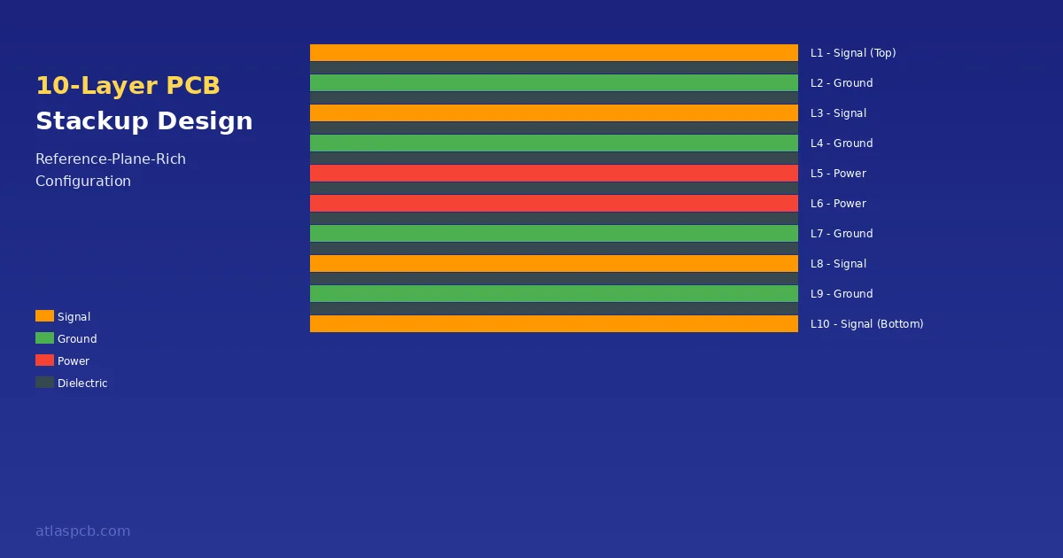
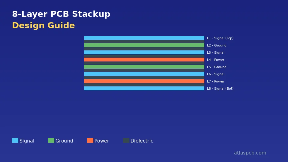
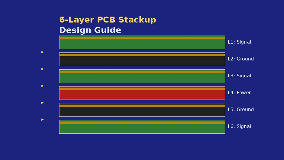
Consider moving to 6 or 8 layers when your design requires more than two impedance-controlled signal layers (a common situation in designs with both high-speed digital buses and sensitive analog interfaces that cannot share layers). The transition is also warranted when routing density exceeds what two signal layers can accommodate within your board area — particularly common with fine-pitch BGA components requiring escape routing through multiple via rows. High-speed interfaces like DDR4, PCIe Gen 3+, and 10 Gbps Ethernet generally benefit from the additional ground reference planes that 6+ layer boards provide, though careful 4-layer design can sometimes accommodate these with reduced margins.
The cost step from 4 to 6 layers is approximately 30-50 percent in prototype quantities, driven primarily by the additional lamination cycle (6-layer boards require two press operations versus one for 4-layer) and the added material layers. This is roughly the same percentage increase as moving from 2 to 4 layers, making the cost progression relatively linear with layer count up to about 8 layers.
Ready to Order Your 4-Layer PCB?
Get an instant quote with DFM review. We support standard and custom stackups with controlled impedance verification on every production lot.
Get Your QuoteSummary and Design Decision Framework
Selecting the right 4-layer stackup requires balancing signal integrity needs, power distribution complexity, EMI requirements, and cost constraints. The decision framework distills to three primary questions:
First, do your signals require identical electromagnetic environments on both outer layers? If yes, choose S-G-G-S with dual ground planes. This ensures symmetric performance regardless of which layer carries your most critical signals, and it eliminates the impedance differences between top (microstrip over ground) and bottom (microstrip over power) that S-G-P-S inherently exhibits.
Second, do you need a dedicated power plane for multiple voltage domains or high-current distribution? If yes, S-G-P-S provides the clearest solution with minimal routing compromise. The segmented power plane handles complex power architectures naturally without consuming signal routing resources.
Third, is maximum shielding from external interference or radiation the primary concern? If yes, G-S-S-G provides the highest isolation at the cost of routing flexibility and assembly complexity.
For the majority of commercial designs — roughly 60 percent of what we manufacture — S-G-P-S provides the best balance of capability, cost, and ease of design. It is the safe default choice when none of the three questions above points strongly toward an alternative.
Whichever configuration you select, communicate it clearly in your fabrication documentation using the template provided in this guide. Specify real material requirements (Tg, prepreg style), state your impedance targets with tolerances, and maintain copper balance for reliable flatness. These simple practices, applied consistently, separate first-pass-success designs from those requiring costly respins.
Reviewed by AtlasPCB Engineering Team
About AtlasPCB — We specialize in complex PCB manufacturing for HDI, RF, and high-reliability applications. Explore our impedance-controlled PCB manufacturing, free engineering DFM review, or get an full PCB manufacturing capabilities . Every order includes free engineering review. Get your quote.
Reviewed by AtlasPCB Engineering Team — IPC-certified manufacturing specialists with 15+ years of production experience in HDI, RF, and high-reliability PCB fabrication. Content based on factory floor data and real customer design reviews.
Frequently Asked Questions
What is the best 4-layer PCB stackup for general use?
How much does a 4-layer PCB cost compared to a 2-layer board?
What prepreg thickness should I use for a 4-layer PCB?
Can I achieve controlled impedance on a 4-layer board?
- 4-layer PCB
- stackup design
- impedance control
- multilayer PCB
- DFM
- PCB manufacturing