· AtlasPCB Engineering · Engineering · 8 min read
Tg150 vs Tg170 FR-4: Choosing the Right Glass Transition Temperature for Your PCB
Compare Tg150 and Tg170 FR-4 laminates for thermal reliability, lead-free assembly, and cost. Engineering decision guide with real CTE data, T288 ratings, and application recommendations.
Quick Decision: Tg150 or Tg170?
| Criterion | Tg150 Acceptable | Tg170 Required |
|---|---|---|
| Layer count | 2-6 layers | 8+ layers |
| Lead-free reflow cycles | Single | Double or rework expected |
| PTH aspect ratio | < 8:1 | > 8:1 |
| Board thickness | < 1.6mm | > 1.6mm |
| Service temperature | < 130C | 130-150C |
| Via reliability class | IPC Class 2 | IPC Class 3 |
| Cost sensitivity | High (consumer) | Moderate (industrial/telecom) |
If your design hits ANY criterion in the Tg170 column, specify Tg170. The cost delta is marginal insurance against field failures that are expensive to diagnose and impossible to rework.
What Glass Transition Temperature Actually Means for Your Board
The Tg value printed on a laminate datasheet represents a phase transition, not a maximum operating temperature—a distinction that causes persistent confusion in PCB specifications. Below Tg, the epoxy resin matrix behaves as a rigid glass with predictable, low thermal expansion. Above Tg, the resin softens into a rubbery state where Z-axis expansion accelerates by 4-6x. The copper barrel plating in your through-hole vias does not share this expansion rate, and that mismatch is what kills boards.
When your PCB enters a lead-free reflow oven with a 260C peak profile, the laminate temperature overshoots Tg by 90-110C for a Tg150 material, or 90C for a Tg170 material. During those 60-90 seconds above Tg, the resin is expanding aggressively in Z while the copper barrel remains relatively stable. Each reflow cycle accumulates fatigue damage in the barrel, particularly at the point of maximum stress—the center of the thickest dielectric span. A Tg170 material gives you 15% less expansion during this critical window, which compounds multiplicatively across multiple reflow exposures.

Thermal Property Comparison: The Numbers That Matter
Understanding the specification differences requires looking beyond just the Tg number. Two parameters matter far more for assembly survival: the Z-axis CTE above Tg and the T288 rating.
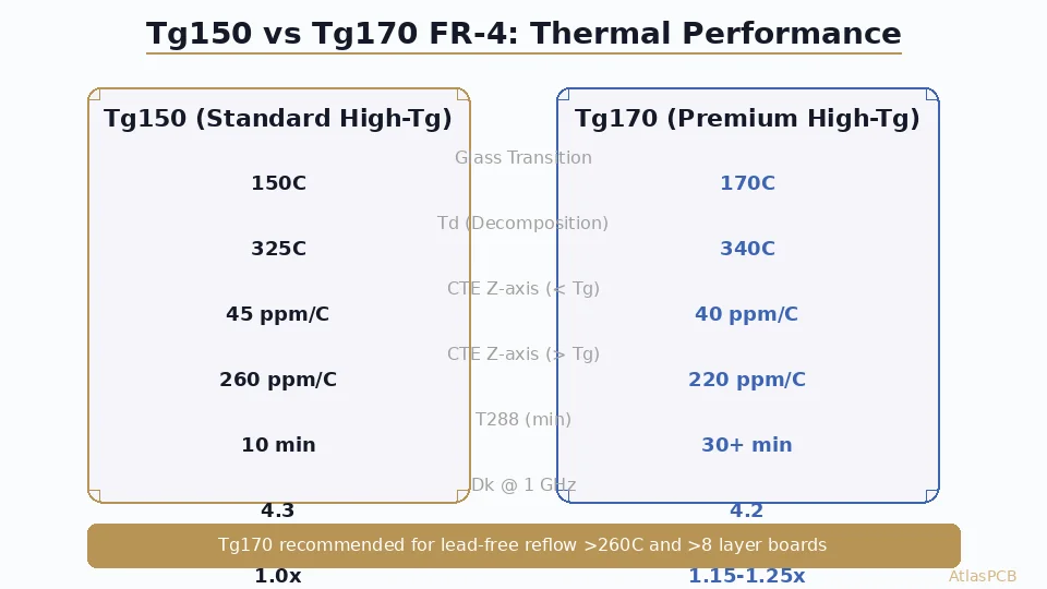
Z-axis CTE above Tg measures how aggressively the laminate expands once it passes through glass transition. Tg150 materials typically exhibit 250-280 ppm/C in this regime, while Tg170 materials hold at 200-230 ppm/C. On a 2.0mm thick board, that 50 ppm/C difference produces approximately 5 microns less total Z-expansion per reflow cycle at 260C peak—enough to shift a borderline via from the “fatigue accumulation” zone into safe territory.
T288 quantifies how many minutes the laminate survives at 288C before delamination occurs. This is arguably the most important reliability indicator for lead-free assembly. Standard Tg150 materials achieve 10-15 minutes; Tg170 materials deliver 30+ minutes. For a board that must survive rework (each rework cycle adds 3-4 minutes of effective T288 exposure), the 3x improvement in Tg170 provides genuine engineering margin rather than theoretical comfort.
| Property | Tg150 (Typical) | Tg170 (Typical) | Why It Matters |
|---|---|---|---|
| Tg (DSC) | 150C | 170C | Onset of accelerated Z-expansion |
| Td (TGA, 5% loss) | 320-330C | 335-345C | Decomposition onset in reflow |
| CTE Z (below Tg) | 42-48 ppm/C | 38-42 ppm/C | Normal service expansion |
| CTE Z (above Tg) | 250-280 ppm/C | 200-230 ppm/C | Reflow barrel stress driver |
| T260 | 20-30 min | 60+ min | Lead-free margin indicator |
| T288 | 10-15 min | 30+ min | Rework survival budget |
| Dk @ 1 GHz | 4.2-4.4 | 4.1-4.3 | Minimal signal impact |
| Moisture absorption | 0.15-0.20% | 0.12-0.18% | Delamination risk factor |
| Cost multiplier | 1.0x | 1.15-1.25x | Laminate material only |
MATERIAL SELECTION SUPPORT
Not Sure Which Tg Rating Your Design Needs?
Upload your Gerber files and stackup. Our engineers review material compatibility with your assembly profile and reliability requirements.
Get Material Recommendation ›Via Reliability: Where Tg Selection Makes or Breaks Your Design
The most common failure mode driven by Tg selection is plated through-hole barrel fatigue. When the laminate expands in Z during reflow, the copper barrel experiences tensile strain. The weakest point is typically at the midspan of the thickest dielectric layer—usually the core in a balanced stackup. Once a microcrack initiates at this point, it propagates across subsequent thermal cycles until the via becomes an open circuit.
For a standard 1.6mm, 4-layer board with 0.3mm drills (aspect ratio 5.3:1), both Tg150 and Tg170 provide comfortable margin through multiple reflow cycles. The calculation changes dramatically for thicker constructions. A 2.4mm, 10-layer board with 0.25mm drills (aspect ratio 9.6:1) pushes Tg150 into marginal territory after a single reflow, and virtually guarantees barrel cracking if rework is attempted. The same construction in Tg170 maintains adequate fatigue margin through two reflows plus one rework cycle.
The IPC-6012 standard addresses this indirectly through minimum copper plating thickness requirements (25 microns average for Class 3), but plating thickness alone cannot compensate for excessive Z-expansion. The laminate must do its part by minimizing the strain imposed on the barrel. In practice, when your aspect ratio exceeds 8:1 or your board thickness exceeds 1.6mm with more than 6 layers, specifying Tg170 is not a conservative choice—it is the engineering-correct choice based on published fatigue data.
MULTILAYER EXPERTISE
Up to 30-Layer Boards with Optimized Tg Selection
AtlasPCB stocks both Tg150 and Tg170 FR-4 in standard thicknesses. We match material grade to your layer count and assembly requirements.
Upload Your Stackup ›Cost Impact and Supplier Considerations
The laminate cost premium for Tg170 over Tg150 runs 15-25% depending on thickness, copper weight, and supplier. On a typical 4-layer, 1.6mm board, this translates to roughly 8-12% increase in total fabrication cost—because laminate is only one component of the manufacturing expense alongside drilling, plating, imaging, and testing.
Where the cost analysis becomes interesting is in the risk-adjusted calculation. A field failure caused by barrel cracking in a deployed product costs orders of magnitude more than the material upgrade—especially in industrial, automotive, or medical applications where recall or warranty replacement is involved. For production volumes above 1000 units in any non-consumer application, the Tg170 premium effectively functions as insurance with a known, bounded cost and a quantifiable reliability improvement.
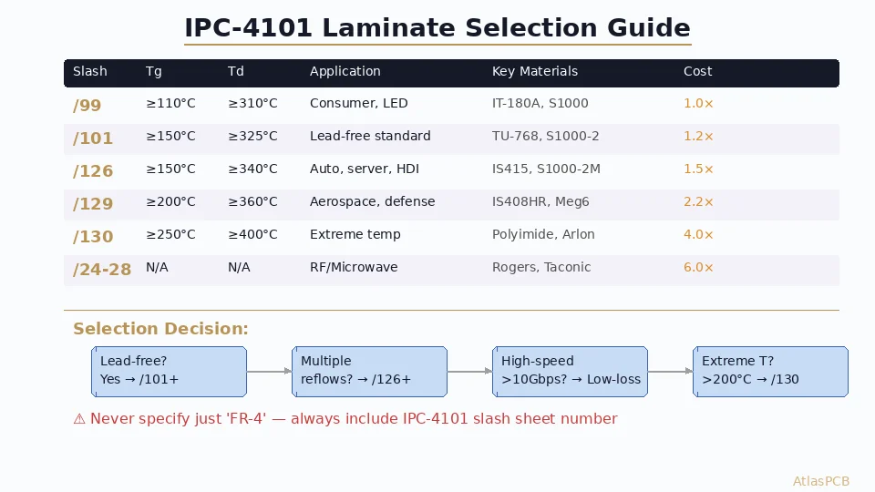
One practical consideration that engineers often overlook: specifying Tg170 rather than a specific laminate brand (such as “Shengyi S1170” or “ITEQ IT-170GS”) gives your fabricator flexibility to use whatever Tg170-rated material is in stock. This avoids procurement delays and can actually reduce cost versus demanding a specific part number. Your fab note should specify “FR-4, Tg >= 170C (DSC), meet IPC-4101/126 or equivalent” rather than calling out a brand.
Application Decision Matrix
Specify Tg150 when all of these are true:
- Board is 2-6 layers, thickness 1.6mm or less
- Single lead-free reflow with no planned rework
- PTH aspect ratio below 8:1 throughout
- Operating temperature below 130C continuous
- IPC Class 2 reliability requirements
- Cost is a primary driver (high-volume consumer)
Specify Tg170 when any of these apply:
- 8 or more layers regardless of thickness
- Board thickness exceeds 1.6mm with any PTH
- Multiple reflow cycles required (double-sided SMT)
- Rework is expected or probable during production
- PTH aspect ratio exceeds 8:1
- Operating temperature 130-150C (automotive underhood, industrial)
- IPC Class 3 reliability requirements
- Product lifecycle exceeds 10 years (infrastructure, aerospace)
Consider Tg180+ (specialty materials) when:
- Controlled Dk/Df needed above 5 GHz
- Operating temperature exceeds 150C
- Halogen-free requirement combined with high-Tg
- Extremely thick constructions (> 3.0mm, > 20 layers)
RAPID PROTOTYPING
Both Tg150 and Tg170 In Stock for Fast Turns
Standard thicknesses ship without material lead time. Complex stackups quoted within 24 hours with material availability confirmed.
Get Instant Quote ›How to Specify Tg in Your Fab Notes
The correct way to call out glass transition temperature in fabrication documentation avoids ambiguity and gives your supplier clear acceptance criteria:
Minimum specification (recommended):
Material: FR-4, Tg >= 170°C (DSC method per IPC-TM-650 2.4.25)
Compliance: IPC-4101/126 or /129 (halogen-free)
Do not specify:
- Just “high-Tg” (ambiguous—could mean 150, 170, or 180)
- A specific brand without “or equivalent” (creates sole-source dependency)
- Tg by TMA method without stating it (TMA reads 10-15C lower than DSC for the same material)
The DSC vs TMA measurement discrepancy is a frequent source of confusion. A material rated “Tg170” by DSC will measure approximately 155-160C by TMA. Always state your measurement method in the fab note. IPC-4101 slash sheets use DSC as the reference method, so specifying by slash sheet number eliminates ambiguity entirely.
ATLASPCB
Ready to Order? We Match Material to Your Requirements
Upload Gerbers with your stackup requirements. We confirm material availability and quote within 24 hours for standard constructions.
Upload Gerber Files ›Related Reading:
About AtlasPCB — We specialize in complex PCB manufacturing for HDI, RF, and high-reliability applications. Explore our aluminum and metal-core PCB services . Every order includes free engineering review. Get your quote.
Reviewed by AtlasPCB Engineering Team — IPC-certified manufacturing specialists with 15+ years of production experience in HDI, RF, and high-reliability PCB fabrication. Content based on factory floor data and real customer design reviews.
- FR-4
- glass transition temperature
- Tg
- PCB material
- lead-free assembly
- thermal reliability
- laminate selection