· AtlasPCB Engineering · Engineering · 9 min read
Aluminum PCB vs FR-4 for Thermal Management: Which Base Material Wins for LED and Power Designs?
Head-to-head comparison of aluminum-backed PCBs versus standard FR-4 for thermal management in LED lighting, power converters, and motor drives. Covers thermal conductivity, cost, reliability, and the design scenarios where each material is the right choice.
30-Second Decision: Aluminum or FR-4?
| Factor | Aluminum PCB | FR-4 (standard) | FR-4 + Thermal Vias |
|---|---|---|---|
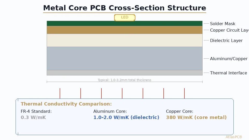
| Thermal conductivity (board) | 1.0-3.0 W/mK (dielectric) | 0.25 W/mK (bulk) | 2-8 W/mK (via array) |
| Base thermal conductivity | 150-220 W/mK (aluminum) | N/A | N/A |
| Junction temp reduction | 20-40C vs bare FR-4 | Baseline | 10-25C vs bare FR-4 |
| Layer count | 1 (standard), 2 (premium) | 1-30 | 2-30 |
| Typical thickness | 1.0-3.2mm total | 0.8-3.2mm | 0.8-3.2mm |
| Cost premium | 1.5-3x over FR-4 | Baseline | 1.2-1.5x (via drilling) |
| Best for | LED, single-sided power | Low-power, complex routing | Multi-layer power + signal |
The rule of thumb: If your design is single-sided and power density exceeds 1 W/cm2, aluminum wins on thermals, reliability, and total system cost. If you need inner signal layers, stick with FR-4 and design a proper thermal via array.
The Physics: Why Aluminum Wins on Single-Layer Thermal Designs
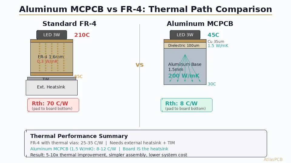
The thermal advantage of aluminum PCBs is not actually about the aluminum itself — it is about eliminating the thermal bottleneck that FR-4 creates. Standard FR-4 has a thermal conductivity of approximately 0.25 W/mK in the through-thickness direction. For a 1.6mm board, that translates to a thermal resistance of about 40 C/W per square centimeter of board area. At even modest power levels, this creates unacceptable temperature rises between the component and any cooling surface below the board.
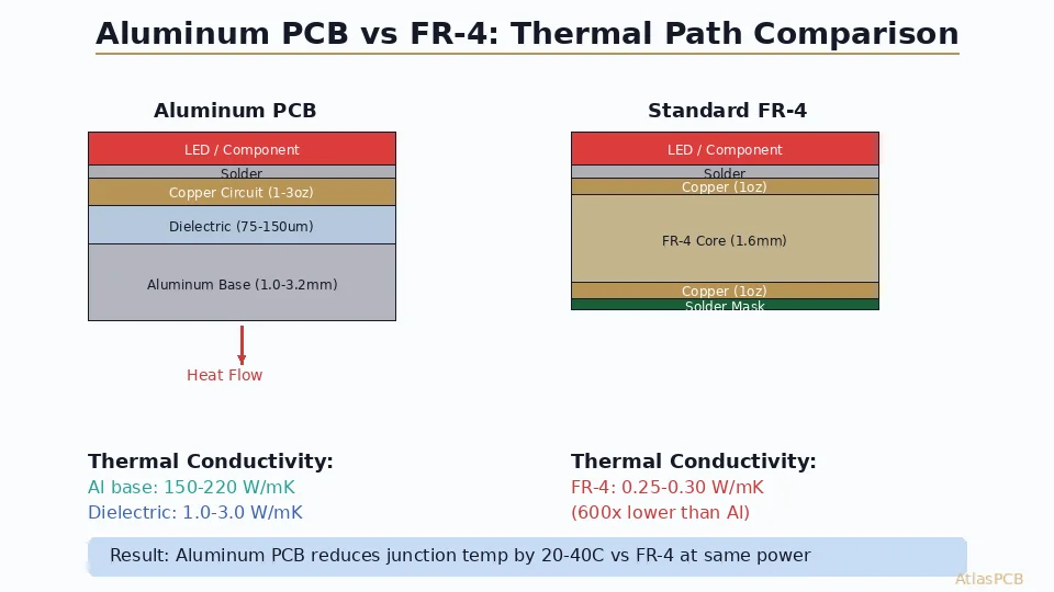
An aluminum PCB replaces that 1.6mm FR-4 core with a three-layer sandwich: copper circuit layer, thin thermally-conductive dielectric (typically 75-150um at 1.0-3.0 W/mK), and an aluminum base plate at 150-220 W/mK. The effective thermal resistance drops to 0.5-2.5 C/W per cm2 — a 15-80x improvement depending on dielectric specification. In our production testing, we consistently measure 20-40C lower junction temperatures on aluminum PCBs versus identical circuit layouts on 1.6mm FR-4 when running LED arrays at rated current.
The thin dielectric layer is the critical design parameter. At 75um thickness with 2.0 W/mK thermal conductivity, you get a per-unit-area thermal resistance of 0.375 Ccm2/W. Move to a 150um dielectric at 1.0 W/mK (the economy option), and thermal resistance jumps to 1.5 Ccm2/W — four times worse. This is why specifying dielectric thickness and thermal conductivity together is essential on your fab drawing; simply calling out “aluminum PCB” without these parameters will get you whatever the manufacturer stocks, which is usually the cheapest option.
From a heat spreading perspective, the aluminum base acts as a nearly isothermal plate beneath your entire circuit. A 1.5mm aluminum base with 200 W/mK conductivity spreads heat laterally so effectively that localized hot spots under individual high-power components get averaged across the entire board area. In our facility, we run thermal imaging on every aluminum PCB design during the DFM review process, and the spreading effect consistently reduces peak temperatures by an additional 5-10C compared to what simple 1D thermal resistance calculations predict.
THERMAL PCB SOLUTIONS
Need a Thermal Design Review for Your LED or Power Board?
Our engineers verify your thermal path design and dielectric specification before production. Aluminum PCBs from 0.8mm to 3.2mm with dielectric up to 3.0 W/mK.
Get Thermal PCB Quote ›Where FR-4 Still Makes Sense (Even for Thermal Designs)
Aluminum PCBs have a fundamental limitation: they are practical only as single-layer or, at most, two-layer designs. The aluminum base prevents through-hole plating and multilayer lamination using standard processes. This means any design requiring inner routing layers, controlled impedance pairs, or component placement on both sides of the board must use FR-4 or a hybrid approach.
For multilayer thermal designs, the correct approach is FR-4 with engineered thermal via arrays. A properly designed via array — 0.3mm drills on 0.6mm pitch filling a thermal pad area — achieves an effective through-board thermal conductivity of 2-8 W/mK depending on via density and copper plating thickness. Our process engineers typically recommend a minimum 30% copper fill ratio (via cross-section area divided by pad area) for power semiconductor thermal pads. At this density, a 1.6mm FR-4 board with filled and capped vias under a QFN exposed pad delivers thermal performance approaching that of a budget aluminum PCB.
The crossover point in our experience is straightforward: if your design has fewer than 50 signal connections and can be routed on a single layer, aluminum PCB gives better thermal performance per dollar. Once you need two or more routing layers, inner ground planes, or controlled impedance, FR-4 with thermal vias becomes the only practical option — and with proper via array design, it delivers adequate thermal performance for most applications up to 3-5 W/cm2 power density.
One hybrid approach gaining traction in high-power LED driver applications is the “thermal coin” or embedded copper slug design: an FR-4 multilayer board with a machined copper or aluminum insert press-fit into a cavity directly below the heat-generating component. This gives you the routing flexibility of FR-4 with localized thermal performance approaching a full metal-core design. AtlasPCB offers this as a custom service for power modules requiring both complex routing and aggressive thermal management.
Cost Reality: Total System Cost Matters More Than Board Cost
Engineers often dismiss aluminum PCBs as “too expensive” based on bare board cost alone, but this misses the system-level cost picture. An aluminum PCB costing $3.50 versus $1.80 for an FR-4 equivalent looks like a 95% premium. However, factor in what aluminum eliminates from the system:
The mechanical heatsink (typically $1.50-5.00 depending on extrusion complexity), thermal interface material ($0.20-1.00 per application), mounting hardware ($0.10-0.30), and the assembly labor to attach the PCB to the heatsink ($0.30-0.80 per unit in automated assembly). When these costs are summed, the FR-4 system often costs more than the aluminum PCB system — and the aluminum approach typically delivers better thermal performance because it eliminates the TIM layer between board and heatsink entirely.
In our manufacturing cost analysis across LED lighting projects, the volume crossover point where aluminum PCB becomes cost-neutral versus FR-4+heatsink is typically 500-2000 units, depending on heatsink complexity. For high-volume consumer LED products (10,000+ units), aluminum PCB almost always wins on total BOM cost.
COMPARE YOUR OPTIONS
Not Sure Which Thermal Approach Fits Your Budget?
Upload your Gerber files and thermal requirements. We quote both aluminum and FR-4+vias options so you can compare total system cost.
Compare Pricing ›Reliability Differences Under Thermal Cycling
Thermal cycling reliability is where the material choice has long-term consequences. Aluminum PCBs and FR-4 boards fail through fundamentally different mechanisms under repeated temperature excursions.
FR-4 boards fail primarily through via barrel cracking and pad lifting when thermal cycling causes differential expansion between copper (17 ppm/C) and FR-4 laminate (50-70 ppm/C in Z-axis). This CTE mismatch generates cumulative fatigue stress on every thermal cycle. For automotive and outdoor LED applications cycling from -40C to +85C, standard FR-4 via structures begin showing resistance increases after 500-1000 cycles per IPC-TM-650 testing.
Aluminum PCBs face a different challenge: the CTE mismatch between aluminum base (23 ppm/C) and copper circuit (17 ppm/C) creates shear stress in the thin dielectric layer. Our reliability testing shows that high-quality aluminum PCBs with proper dielectric adhesion survive 1000+ thermal cycles from -40C to +150C without delamination — but economy-grade products from vendors cutting corners on dielectric adhesion can fail in under 200 cycles. The key specification to control is peel strength: demand minimum 1.0 N/mm per IPC-TM-650 Method 2.4.8 on your purchase order.
For applications requiring both thermal management and extreme reliability — automotive LED headlamps, industrial motor drives, aerospace power converters — copper-base MCPCB provides the gold standard. Copper’s CTE (17 ppm/C) matches the circuit copper perfectly, eliminating the dominant failure mechanism. The tradeoff is weight (copper is 3.3x heavier than aluminum) and cost (2-4x premium over aluminum MCPCB), which makes it practical only for high-reliability applications where failure cost far exceeds material cost.
METAL CORE PCB MANUFACTURING
Aluminum and Copper-Base MCPCB Production
Single and double-sided MCPCB with dielectric thermal conductivity from 1.0 to 3.0 W/mK. IPC Class 2 and Class 3 available.
Specification Checklist: What to Call Out on Your Fab Drawing
Getting the thermal performance you designed for requires precise specification. We see engineers lose 30-50% of their thermal budget by under-specifying the aluminum PCB callouts. Here is what must appear on your fabrication drawing:
For aluminum PCB: specify base material thickness (1.0, 1.5, 2.0, or 3.2mm are standard), base alloy (5052 or 6061 — 5052 is standard for PCB), dielectric thermal conductivity (1.0, 1.5, 2.0, or 3.0 W/mK), dielectric thickness (75um or 100um standard; 150um for high-voltage isolation), and copper weight (1oz standard, 2oz for high-current traces). Missing any of these leaves the manufacturer to choose their cheapest stock — which is typically 1.5mm / 5052 / 1.0 W/mK / 100um / 1oz.
For FR-4 thermal via arrays: specify via drill diameter (0.3mm standard), via pitch (0.6-1.0mm), whether vias should be filled and capped (required if components mount over the array), and plating thickness (minimum 25um for thermal performance). A via array note on your fab drawing such as “Thermal via array per detail A: 0.3mm drill, 0.6mm pitch, copper-filled, cap-plated per IPC-4761 Type VII” eliminates ambiguity.
ATLASPCB
Ready to Order Your Thermal PCB?
Upload your Gerber files with thermal specifications. Our engineers review your dielectric and via array specs before production to ensure you get the thermal performance you designed for.
Upload Gerber Files ›Reviewed by AtlasPCB Engineering Team — 15+ years in advanced PCB fabrication for RF, HDI, and rigid-flex applications.
Related Reading:
About AtlasPCB — We specialize in complex PCB manufacturing for HDI, RF, and high-reliability applications. Explore our aluminum PCB manufacturing . Every order includes free engineering review. Get your quote.
Reviewed by AtlasPCB Engineering Team — IPC-certified manufacturing specialists with 15+ years of production experience in HDI, RF, and high-reliability PCB fabrication. Content based on factory floor data and real customer design reviews.
- aluminum PCB
- metal core PCB
- thermal management
- LED PCB
- MCPCB