· AtlasPCB Engineering · Engineering · 4 min read
SMT vs Through-Hole Assembly: Which PCB Technology Is Right for You?
Compare Surface Mount Technology (SMT) and through-hole assembly — learn the differences in component types, soldering processes, mechanical strength, and when to use each approach.

The two fundamental component mounting technologies in PCB assembly are Surface Mount Technology (SMT) and Through-Hole Technology (THT). Each has distinct advantages, and many modern boards use both. This guide helps you understand when to use each.
Surface Mount Technology (SMT)
How It Works
Components are placed directly onto solder paste deposited on the PCB surface pads, then heated in a reflow oven to form solder joints. No holes are drilled for component leads.
Process Flow
- Solder paste printing: A stencil applies solder paste to pads
- Pick and place: Automated machines place components at rates of 20,000-80,000 components per hour
- Reflow soldering: The board passes through a reflow oven with controlled temperature zones (preheat → soak → reflow peak at 235-250°C → cooling)
- AOI/X-ray inspection: Automated inspection catches defects
Component Types
- Chip resistors/capacitors (0201, 0402, 0603, 0805, 1206)
- QFP (Quad Flat Package) — 0.4-1.0mm pitch
- BGA (Ball Grid Array) — 0.4-1.27mm pitch
- QFN/DFN (leadless packages)
- SOT-23, SOT-223, SOIC, SSOP, TSSOP
Advantages
- Smaller board size: Components are 50-80% smaller than THT equivalents
- Higher density: Both sides of the board can carry components
- Faster assembly: Fully automated high-speed placement
- Better high-frequency performance: Shorter leads mean less parasitic inductance
- Lower cost at volume: Automation reduces per-unit assembly cost
- Weight reduction: Smaller components weigh less
Disadvantages
- Mechanical fragility: Solder joints are weaker under mechanical stress (vibration, flex)
- Thermal cycling stress: Solder fatigue from repeated heating/cooling
- Repair difficulty: Reworking fine-pitch components requires specialized equipment
- Not suitable for high-power connectors: Can’t handle the mechanical forces of cable insertion/removal
Through-Hole Technology (THT)
How It Works
Components with wire leads are inserted through holes drilled in the PCB, then soldered from the opposite side. The solder joint wraps around the lead inside the plated hole.
Process Flow
- Component insertion: Manual or semi-automated insertion of leaded components
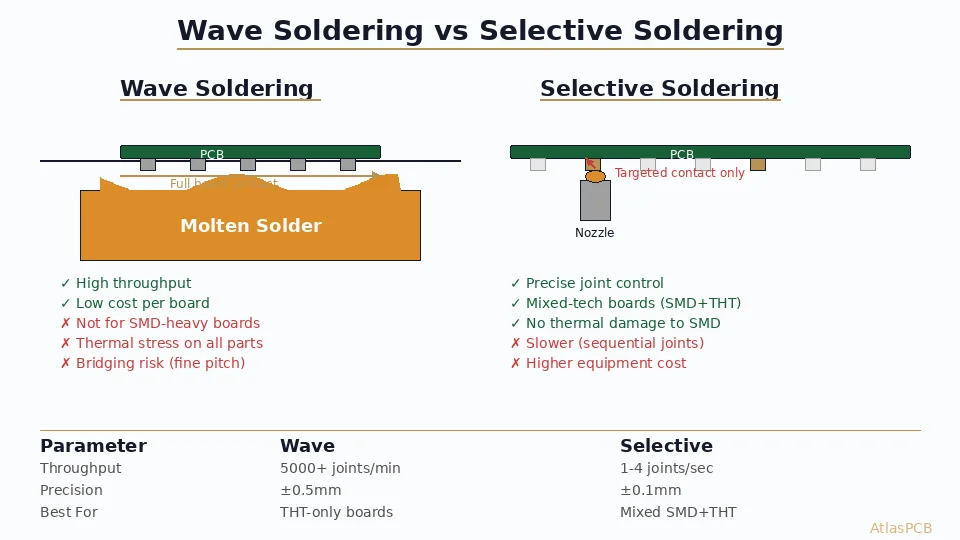
- Wave soldering: The board’s bottom side passes over a wave of molten solder
- Selective soldering: For mixed-technology boards, a programmable nozzle applies solder only to THT components
- Inspection and touch-up: Visual inspection and manual soldering corrections
Component Types
- DIP (Dual In-line Package) ICs
- Axial resistors and capacitors
- Electrolytic capacitors (radial)
- Connectors (USB, HDMI, DC power, headers)
- Transformers and inductors
- Relays
- Through-hole power semiconductors (TO-220, TO-247)
Advantages
- Superior mechanical strength: The lead-through-hole solder joint provides much stronger mechanical bond
- Easy prototyping: Hand-soldering is straightforward
- High-power handling: Large components for high current and high voltage
- Thermal resilience: Better solder joint reliability under thermal cycling
- Connector durability: Withstands repeated insertion/removal forces
Disadvantages
- Larger footprint: Components take more board space
- Single-side mounting (mostly): Components only on one side; holes consume routing space on all layers
- Slower assembly: Manual or semi-automated insertion is slower
- Higher assembly cost: More labor-intensive
- Drill hole requirements: Every through-hole component needs a drilled, plated hole
Comparison Table
| Feature | SMT | Through-Hole |
|---|---|---|
| Component size | Very small (0201 = 0.6x0.3mm) | Large (DIP-8 = 10x7mm) |
| Board density | Very high | Low-Medium |
| Assembly speed | 20,000-80,000 CPH | 500-3,000 CPH |
| Mechanical strength | Moderate | Excellent |
| High-frequency | Excellent (low parasitics) | Poor (long leads) |
| Power handling | Limited | Excellent |
| Rework | Difficult (fine-pitch) | Easy (hand soldering) |
| Cost (high volume) | Low | High |
| Cost (low volume) | Medium | Low (manual) |
| Dual-side mounting | Yes | Limited |
Mixed Technology Assembly
Most modern PCBs use mixed technology — SMT for the majority of components, with through-hole for specific parts that need mechanical strength or power handling:
- SMT: ICs, passives, LEDs, small semiconductors
- THT: Connectors, large capacitors, transformers, power devices, mounting hardware
Mixed Assembly Process
- SMT first: Print paste → place SMD → reflow (top side)
- Bottom SMT (if needed): Glue → place → reflow or wave
- THT last: Insert through-hole components → selective or wave soldering
When to Choose SMT
- High-density, space-constrained designs
- High-speed or high-frequency circuits
- Large production volumes (>1,000 units)
- Consumer electronics and portable devices
- When weight and size matter
When to Choose Through-Hole
- High mechanical stress environments (automotive, industrial)
- Power electronics (>5A per connection)
- Connectors and mechanical interfaces
- Prototyping and small batch production
- Education and hobby projects
Conclusion
SMT dominates modern electronics manufacturing due to its size, speed, and cost advantages at scale. Through-hole remains essential for mechanical strength, power handling, and specific connector requirements. The best designs combine both technologies strategically, using SMT where possible and THT where needed.
Further Reading
- [HDI PCB Design Guide: Stackup Rules, Via Structures & DFM Checklist]/blog/hdi-pcb-design-guide/)
- [PCB Manufacturer with Engineering Review: Why Human DFM Audit Matters]/blog/pcb-manufacturer-engineering-review/)
About AtlasPCB — We specialize in complex PCB manufacturing for HDI, RF, and high-reliability applications. Explore our PCB assembly services . Every order includes free engineering review. Get your quote.
Reviewed by AtlasPCB Engineering Team — IPC-certified manufacturing specialists with 15+ years of production experience in HDI, RF, and high-reliability PCB fabrication. Content based on factory floor data and real customer design reviews.
- SMT
- through-hole
- pcb assembly
- soldering