· AtlasPCB Engineering · Engineering · 4 min read
PCB Trace Antenna Design: WiFi, Bluetooth, NFC, and LoRa Antenna Guide
Design PCB trace antennas for wireless applications — inverted-F, meander line, and loop antenna structures for WiFi, Bluetooth, NFC, LoRa, and cellular IoT with layout and tuning guidelines.

PCB trace antennas eliminate the cost and size of external antennas, making them ideal for IoT devices, wearables, and compact wireless products. This guide covers the most common PCB antenna types and practical design guidelines.
Why PCB Trace Antennas?
| Feature | Trace Antenna | Chip Antenna | External Antenna |
|---|---|---|---|
| Cost | Free (copper) | $0.10-0.50 | $1-10 |
| Size | Medium-Large | Small | External |
| Performance | Good (if designed well) | Moderate | Best |
| Customization | Full control | Limited | N/A |
| Ground plane sensitivity | High | Medium | Low |
Common PCB Antenna Types
1. Inverted-F Antenna (IFA/PIFA)
- Most popular PCB antenna for WiFi/Bluetooth
- Quarter-wave structure with ground connection
- Compact: ~30x8mm for 2.4 GHz
- Impedance tunable by adjusting feed and ground point spacing
- Typical bandwidth: 100-200 MHz (sufficient for 2.4 GHz WiFi/BT)
2. Meander Line Antenna
- Serpentine trace that reduces physical length while maintaining electrical length
- Very compact but narrower bandwidth
- Common for sub-1 GHz (LoRa 868/915 MHz, cellular IoT)
- Size reduction: 50-70% compared to straight dipole
3. Loop Antenna
- Primarily used for NFC (13.56 MHz)
- Rectangular or circular loop matching the NFC reader coil
- Typical size: 30x40mm to 50x50mm
- Resonant with external matching capacitors
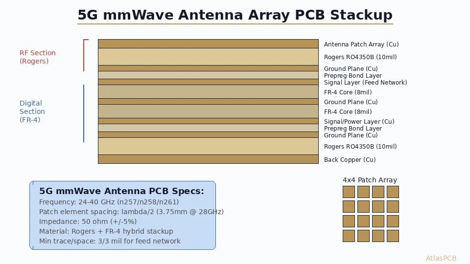
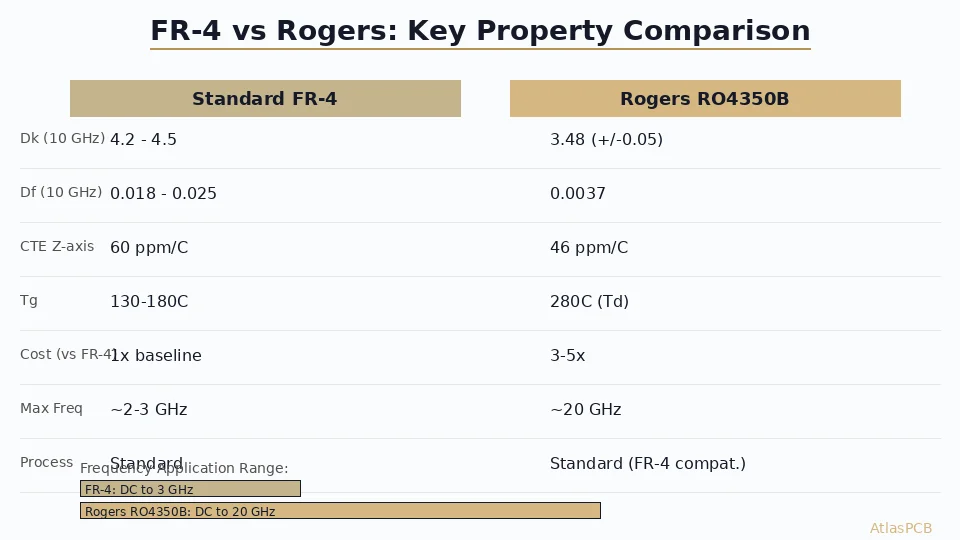
4. Microstrip Patch Antenna
- Used for GPS (1.575 GHz) and mmWave (24-77 GHz)
- Square or circular patch on top layer, ground plane below
- Directional (radiates upward)
- Size: ~46x46mm for GPS, ~3x3mm for 77 GHz

Design Guidelines
Ground Plane Rules
- Keep-out zone: No ground copper under the antenna element and within 2-3mm around it
- Ground plane size: Minimum lambda/4 in the dominant direction (31mm for 2.4 GHz)
- Ground plane edge: Antenna should be at the board edge, with ground plane extending away from it
- Ground clearance: The keep-out zone is critical — ground copper too close detunes the antenna
Matching Network
Every PCB antenna needs a matching network to achieve 50 ohm impedance:
- Pi network: Series inductor + two shunt capacitors (most common)
- Component values: Typically 1-10nH inductors, 0.5-5pF capacitors
- Placement: Directly at the antenna feed point, before the transmission line to the RF IC
- Tuning: Requires a VNA (Vector Network Analyzer) and iterative component adjustment
Transmission Line from IC to Antenna
- 50 ohm controlled impedance trace
- As short as possible (every mm adds loss)
- No bends, no vias if possible
- Ground coplanar waveguide (GCPW) recommended
Frequency-Specific Guidelines
WiFi/Bluetooth 2.4 GHz
- Antenna length: ~31mm (quarter-wave) or ~15mm (meander)
- Board size: minimum 30x60mm for reasonable performance
- Keep antenna away from battery and metal chassis
- Return loss target: <-10dB across 2.4-2.5 GHz
WiFi 5 GHz (5.15-5.85 GHz)
- Antenna length: ~14mm
- Dual-band antennas cover both 2.4 and 5 GHz
- Tighter layout requirements (smaller wavelength)
LoRa 868/915 MHz
- Antenna length: ~82mm (quarter-wave at 915 MHz)
- Meander or helical to fit on smaller boards
- Ground plane: minimum 80x40mm
NFC 13.56 MHz
- Loop antenna: 3-5 turns, 30x40mm typical
- External matching: series resonance capacitor + impedance matching
- No ground plane under the loop
- Ferrite sheet behind loop if metal is nearby
GPS L1 1.575 GHz
- Patch antenna: 25x25mm (with high-Dk ceramic) or 46x46mm (FR-4)
- Must face sky — place on top of device
- Active antenna with LNA recommended for sensitivity
Common Mistakes
- Ground plane under antenna element — detunes and kills efficiency
- Antenna too close to metal enclosure — massive detuning
- No matching network — poor impedance match wastes radiated power
- Ignoring user’s hand — human body detunes 2.4 GHz antennas significantly
- Antenna on inner layer — must be on outer layer for radiation
- Long feed line — every centimeter adds 0.3-0.5dB loss at 2.4 GHz on FR-4
Testing and Tuning
Required Equipment
- VNA (Vector Network Analyzer): Measures S11 (return loss) and impedance
- Anechoic chamber: For radiation pattern and gain measurement (or use outdoor range)
Tuning Process
- Fabricate board with initial antenna design
- Measure S11 with VNA — identify resonant frequency and impedance
- Adjust matching network components to center frequency and achieve <-10dB return loss
- Measure radiation pattern and efficiency (target >50% for PCB antenna)
- Test with enclosure and user hand proximity
Conclusion
PCB trace antennas are a cost-effective solution for wireless products when designed properly. Success requires following ground plane rules, including a tunable matching network, and planning for VNA-based tuning. For first-time designs, start with reference designs from IC manufacturers (TI, Nordic, Espressif all publish recommended antenna layouts) and adapt to your board geometry. PCB antenna design is as much art as science — plan for at least 2-3 tuning iterations.
Further Reading
[Controlled Impedance PCB: Design, Stackup & Testing Explained]/blog/controlled-impedance-pcb/)
[PCB Grounding Techniques: Star, Split, and Solid Ground Plane Strategies]/blog/pcb-grounding-techniques/)
[IPC Class 3 Requirements: The Complete Guide for Designers]/blog/ipc-class-3-requirements/)
About AtlasPCB — We specialize in complex PCB manufacturing for HDI, RF, and high-reliability applications. Explore our full PCB manufacturing capabilities, or get an instant online quote . Every order includes free engineering review. Get your quote.
Reviewed by AtlasPCB Engineering Team — IPC-certified manufacturing specialists with 15+ years of production experience in HDI, RF, and high-reliability PCB fabrication. Content based on factory floor data and real customer design reviews.
- antenna design
- WiFi
- Bluetooth
- IoT