· AtlasPCB Engineering · Engineering · 6 min read
Ionic Contamination Testing for PCB Assembly: No-Clean Flux Residue, SIR, and IPC-J-STD-001 Compliance
Complete guide to ionic contamination control in PCB assembly. Covers ROSE testing, SIR (Surface Insulation Resistance), ion chromatography, no-clean flux residue behavior, IPC cleanliness standards, and practical contamination prevention strategies for high-reliability electronics.
Why Ionic Contamination Matters for PCB Reliability
Ionic contamination is the invisible killer of electronics reliability. A PCB assembly can pass all electrical tests at room temperature and still fail catastrophically in the field when humidity, voltage bias, and surface ions combine to create electrochemical migration — tin dendrites growing between adjacent conductors until a short circuit destroys the product.
As component pitches shrink below 0.4mm and operating voltages push 3.3V across 100µm gaps, the electrochemical driving force for migration increases while the distance dendrites must travel decreases. Understanding and controlling ionic contamination is no longer optional for reliable electronics.
Sources of Ionic Contamination
Process-Related Contaminants
| Source | Ionic Species | Typical Level | Risk |
|---|---|---|---|
| Flux residue (unreacted) | Chloride, bromide, organic acids | 1-10 µg/cm² | High |
| Solder paste vehicle | Glycols, amines, surfactants | 0.5-3 µg/cm² | Medium |
| Wave solder flux | Chloride, halide activators | 2-15 µg/cm² | High |
| Hand soldering flux | Varies widely | 1-20 µg/cm² | Variable |
| PCB bare board (post-fab) | Sulfate, chloride from plating | 0.5-2 µg/cm² | Low-Medium |
Environmental and Handling Contaminants
| Source | Ionic Species | Prevention |
|---|---|---|
| Fingerprints | NaCl, urea, lactic acid | Gloves, ESD handling procedures |
| Packaging materials | Sulfur compounds, chloride | Low-ionic packaging specification |
| Storage humidity | Absorbed atmospheric acids | Dry cabinet (<10% RH) storage |
| Cleaning water | Ca²⁺, Mg²⁺, Cl⁻ | DI water (>18 MΩ·cm) rinse |
Testing Methods
ROSE Testing (IPC-TM-650 2.3.25)
ROSE (Resistivity of Solvent Extract) is the fastest and most common production-level contamination test:
Procedure:
- Board immersed in 75% IPA / 25% DI water solution (pre-measured resistivity)
- Solution circulated for 1 hour at room temperature (or 15 min heated to 40°C)
- Conductivity change measured continuously
- Total ionic contamination calculated as µg/cm² NaCl equivalent
Pass/Fail Criteria (IPC-J-STD-001):
- Class 1 (general): ≤ 1.56 µg/cm² NaCl eq.
- Class 2 (dedicated service): ≤ 1.56 µg/cm² NaCl eq.
- Class 3 (high performance): ≤ 1.56 µg/cm² (same limit, tighter process control expected)
Limitations:
- Bulk measurement — cannot localize contamination
- Rosin encapsulation can prevent extraction
- No-clean flux residues may not fully dissolve in test solvent
- Cannot distinguish between harmful ionic species and benign residues
Surface Insulation Resistance (SIR) — IPC-TM-650 2.6.3.7
SIR is the gold standard for assessing whether contamination will cause field failures:
Procedure:
- IPC-B-24 or IPC-B-25 test coupon (interdigitated comb pattern, 12.5 mil line/space)
- Apply product-equivalent flux/solder process to coupon
- Place in environmental chamber: 85°C / 85% RH
- Apply 50V DC bias between comb teeth
- Measure insulation resistance at 24, 96, 168, and 500+ hours
- Monitor for dendrite growth (visual inspection at intervals)
Pass Criteria:
- Insulation resistance ≥ 100 MΩ throughout test duration
- No visible dendrite growth
- No electromigration evidence
Why SIR is Superior: SIR replicates the actual failure mechanism — ionic migration under bias and humidity. A board that passes ROSE but fails SIR has residues that are benign under test extraction conditions but corrosive in real environments. This is common with certain no-clean flux chemistries.
Reliable PCB Assembly for Critical Applications
AtlasPCB's assembly process includes ionic contamination monitoring, SIR-validated flux systems, and IPC-J-STD-001 Class 3 workmanship standards. Every production lot is ROSE-tested.
Get Assembly Quote →Ion Chromatography (IC) — IPC-TM-650 2.3.28
When ROSE testing shows contamination but you need to identify the source:
Procedure:
- Extract contaminants from specific board areas using localized extraction cells
- Analyze extract through ion chromatography column
- Identify and quantify individual ionic species
Detectable Species:
- Anions: Chloride, bromide, fluoride, sulfate, nitrate, phosphate, formate, acetate, adipate, succinate
- Cations: Sodium, potassium, ammonium, calcium, magnesium, lithium
Diagnostic Power:
- High chloride + bromide → Flux activator residue
- Sulfate → Plating bath dragout
- Sodium + chloride → Fingerprint contamination
- Calcium + sulfate → Tap water residue
- Weak organic acids (WOA) → No-clean flux decomposition products
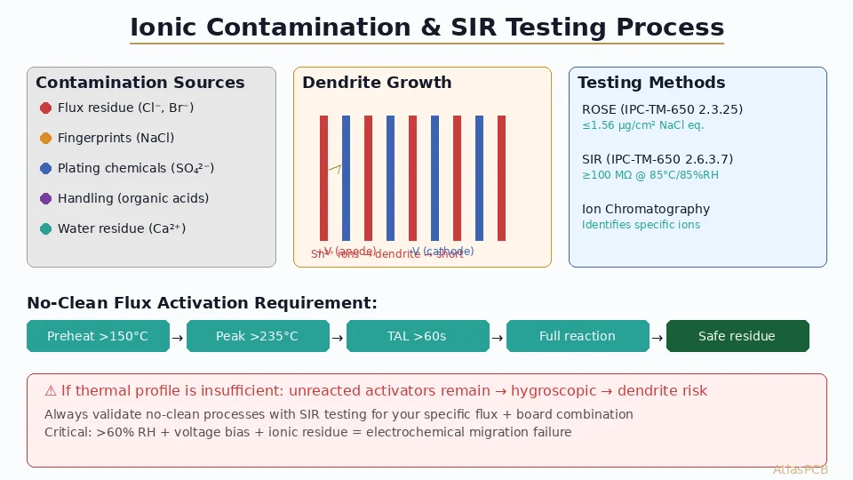
No-Clean Flux: The Reliability Paradox
How No-Clean Works (When It Works)
No-clean flux contains mild organic acid activators (ROL0 or ROL1 classification per IPC J-STD-004) designed to:
- Remove surface oxides during preheat (150-200°C)
- React completely with copper/tin oxides during peak reflow (235-260°C)
- Leave behind only benign, non-ionic, non-hygroscopic residue
The key word is “completely.” When the thermal profile delivers adequate time above 200°C (typically 60-90 seconds), the activator system fully reacts. The remaining residue is inert metal-organic salt encapsulated in rosin or resin.
When No-Clean Fails
Insufficient Thermal Activation:
- Preheat too short → unreacted adipic/succinic acid remains
- Peak temperature too low → activators don’t fully decompose
- Large thermal mass components → local temperature 20-40°C below oven setpoint
- Board edges and corners → 15-25°C cooler than center
Incompatible Process Combinations:
- Mixing flux brands between paste and rework
- Using no-clean paste with water-soluble rework flux
- Conformal coating over unreacted no-clean residue (traps moisture)
Environmental Activation After Assembly:
- High humidity (>60% RH) causes hygroscopic residue to absorb moisture
- Voltage bias drives ionic migration in the absorbed moisture film
- Temperature cycling condenses moisture under components (trapped spaces)
Best Practices for No-Clean Reliability
- Profile validation: Ensure all board locations reach ≥200°C for ≥60 seconds above liquidus
- Component thermal shadow: Use TC measurements under large QFPs and BGAs
- SIR qualification: Test every new flux/paste combination before production
- Humidity specification: Specify maximum operating humidity in product requirements
- Storage control: Keep assembled boards in <10% RH cabinets if not immediately conformal coated
- No rework mixing: If rework is needed, use the same flux chemistry as primary process
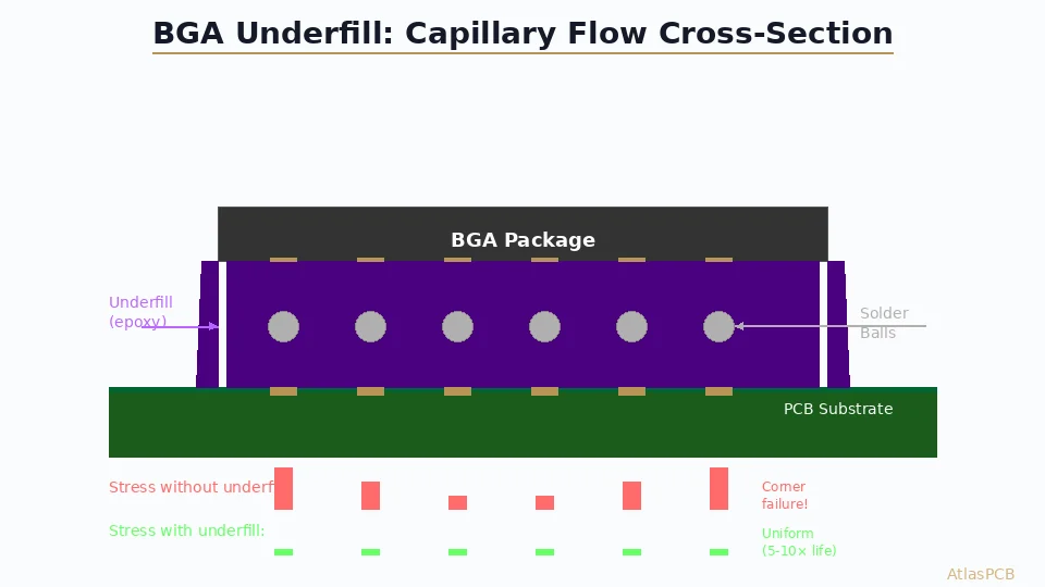
Electrochemical Migration: The Failure Mechanism
Dendrite Growth Process
- Electrolyte formation: Moisture absorbs onto contaminated surface, dissolving ionic species
- Anodic dissolution: Positive electrode (anode) oxidizes: Sn → Sn²⁺ + 2e⁻
- Ion transport: Sn²⁺ ions migrate through electrolyte toward cathode (negative electrode)
- Cathodic deposition: Sn²⁺ + 2e⁻ → Sn (metallic tin deposits as dendrite)
- Growth: Dendrite extends from cathode toward anode until bridging occurs
Critical parameters:
- Voltage: Higher bias accelerates migration (>2V becomes significant at <200µm pitch)
- Humidity: >60% RH required to form continuous electrolyte film
- Temperature: Higher temperature increases ionic mobility
- Contamination: Provides additional ions and hygroscopic nucleation sites
Prevention Hierarchy
- Eliminate contamination: Clean if possible (water-soluble flux) or ensure full activation (no-clean)
- Reduce voltage: Keep maximum DC bias below 5V for fine-pitch circuits
- Control humidity: Conformal coating, potting, or hermetic sealing
- Increase spacing: Design for maximum conductor-to-conductor clearance
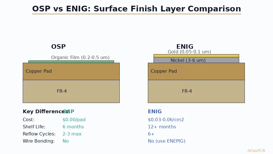
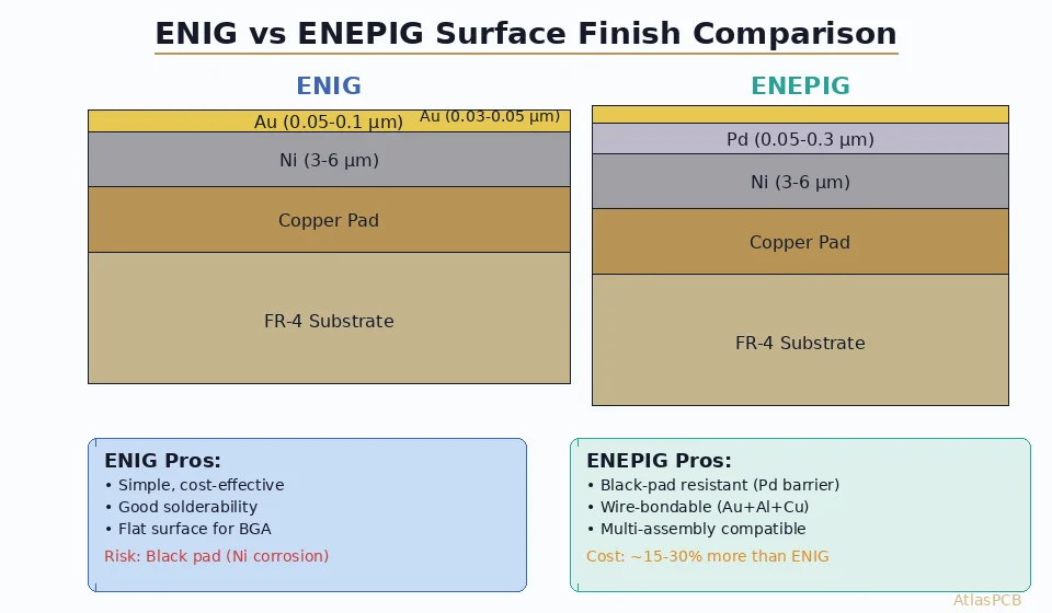
- Material selection: Use resistive barrier layers (Ni/Au finish vs bare tin)
IPC Cleanliness Standards Summary
| Standard | Scope | Key Requirement |
|---|---|---|
| IPC-J-STD-001 | Assembly cleanliness | ≤1.56 µg/cm² NaCl eq. (ROSE) |
| IPC-5704 | Cleanliness of bare PCBs | ≤1.56 µg/cm² before assembly |
| IPC-CH-65 | Cleaning guideline | Process development procedures |
| IPC-9202 | SIR qualification | Material/process validation |
| IPC-9203 | IC guidelines | Localized contamination analysis |
Process Control Recommendations
For Assembly Operations
- Incoming inspection: ROSE test bare boards (catch plating contamination)
- Process monitoring: Weekly SIR coupons run alongside production
- Reflow profile: Validate with TC measurements quarterly and after any paste change
- Handling: Nitrile gloves mandatory, ESD smocks to prevent skin contact
- Storage: Assembled boards in dry cabinets within 4 hours of reflow
- Rework control: Localized cleaning after any hand soldering operation
For Design Engineers
- Spacing: Maintain ≥150µm conductor spacing where possible for SIR margin
- Solder mask: Specify solder mask between all fine-pitch pads (acts as moisture barrier)
- Via tenting: Tent vias near fine-pitch areas to prevent flux wicking underneath
- Test accessibility: Include ionic contamination test pads in production panel borders
- Conformal coating: Specify for any product operating >60% RH environment
Further Reading
- AOI and SPI Inspection in PCB Assembly Quality Control
- Reflow Soldering Profile Optimization for Lead-Free Assembly
- SMT vs Through-Hole Assembly: When to Use Each
- PCB Conformal Coating Selection Guide
Building electronics for harsh or high-reliability environments? AtlasPCB’s IPC-certified assembly line includes ROSE testing, SIR-validated processes, and ionic contamination monitoring as standard. Get your assembly quote →
About AtlasPCB — We specialize in complex PCB manufacturing for HDI, RF, and high-reliability applications. Explore our PCB assembly services, or get an full PCB manufacturing capabilities . Every order includes free engineering review. Get your quote.
Reviewed by AtlasPCB Engineering Team — IPC-certified manufacturing specialists with 15+ years of production experience in HDI, RF, and high-reliability PCB fabrication. Content based on factory floor data and real customer design reviews.
- pcb assembly
- ionic contamination
- SIR testing
- no-clean flux
- IPC standards
- reliability