· AtlasPCB Engineering · Engineering · 14 min read
PCB Etch Compensation: Trace Width Accuracy
How etch compensation maintains trace width accuracy in PCB production. Covers etch factor, copper weight effects, and fine-line DFM.
Understanding Etch Compensation in PCB Manufacturing
Every copper trace on a PCB starts wider on the artwork than it ends up on the finished board. This is not an error—it is deliberate engineering called etch compensation. During chemical etching, the etchant dissolves copper vertically through the full thickness but also attacks sideways under the photoresist, a phenomenon called undercut. The result is a finished trace that is narrower than the resist pattern, with a trapezoidal cross-section rather than the ideal rectangle.
Etch compensation counteracts undercut by making the artwork features wider than the desired finished dimensions. Without it, every trace would be undersized, impedance would shift high, current capacity would drop, and fine-pitch features would risk opening entirely.
This guide covers the physics of copper etching, etch factor calculation, compensation values for common copper weights, the impact on impedance control and fine-line PCBs, and practical DFM guidelines for getting trace width right in production. For foundational trace geometry rules, see our [Trace width and spacing rules]/blog/pcb-design-rules-trace-width-spacing/).
The Physics of Copper Etching
How Chemical Etching Works
PCB etching uses a chemical solution (etchant) to dissolve exposed copper that is not protected by photoresist or tin plating. The two dominant etchant chemistries in production are:
- Alkaline ammoniacal (NH₃/NH₄Cl) — Used for inner layers and dry film resist processes. pH 8.0–8.5, operating temperature 48–52 °C. Moderate etch rate, good for fine features.
- Cupric chloride (CuCl₂) — Used for outer layers with tin/lead or tin resist. pH < 1.0, operating temperature 50–55 °C. Faster etch rate, higher etch factor.
Both chemistries are isotropic at the microscale—they etch in all directions equally when copper is exposed. However, because the etchant reaches the copper surface from the top (spray etching), the vertical etch rate is somewhat faster than lateral undercut due to fluid dynamics and fresh etchant replenishment from above.
Undercut and the Trapezoidal Profile
When the etchant dissolves copper downward through its full thickness, it simultaneously creeps laterally under the resist edges. This lateral removal is called undercut. The result is a trace cross-section that resembles a trapezoid: the top width (at the resist line) is wider than the bottom width (at the laminate surface).
For a typical 1 oz (35 µm) copper trace etched with an etch factor of 3.0:
- Vertical etch depth: 35 µm
- Lateral undercut per side: 35 µm ÷ 3.0 = 11.7 µm
- Total width reduction: 2 × 11.7 = 23.3 µm (approximately 0.92 mil)
- Top width is approximately 23.3 µm wider than bottom width
This trapezoidal shape is inherent to subtractive etching and cannot be eliminated—only managed through compensation and process control.
Etch Factor: Definition and Calculation
What Is Etch Factor?
Etch factor (EF) is the ratio of vertical etch depth to lateral undercut:
EF = Copper Thickness / Lateral Undercut (per side)
A higher etch factor indicates less lateral etching relative to vertical depth, meaning more vertical sidewalls and less width loss. Etch factor is influenced by:
- Etchant chemistry — Cupric chloride typically produces higher etch factors (2.5–5.0) than alkaline ammoniacal (2.0–4.0)
- Spray pressure and nozzle configuration — Higher top-side spray pressure drives fresh etchant downward, favoring vertical etch
- Conveyor speed — Faster conveyor reduces overall dwell time, but the etch factor ratio remains roughly constant
- Copper thickness — Thinner copper tends to yield higher effective etch factors because lateral undercut has less time to develop
- Feature density — Isolated traces etch slightly differently than dense arrays due to etchant pooling
Etch Factor by Copper Weight
| Copper Weight | Thickness (µm) | Typical Etch Factor (Alkaline) | Typical Etch Factor (CuCl₂) | Undercut per Side (µm) — Alkaline | Undercut per Side (µm) — CuCl₂ |
|---|---|---|---|---|---|
| ⅓ oz | 12 | 3.0–4.0 | 3.5–5.0 | 3.0–4.0 | 2.4–3.4 |
| ½ oz | 17.5 | 2.8–3.5 | 3.0–4.5 | 5.0–6.3 | 3.9–5.8 |
| 1 oz | 35 | 2.5–3.5 | 2.8–4.0 | 10.0–14.0 | 8.8–12.5 |
| 2 oz | 70 | 2.0–3.0 | 2.5–3.5 | 23.3–35.0 | 20.0–28.0 |
| 3 oz | 105 | 1.8–2.5 | 2.0–3.0 | 42.0–58.3 | 35.0–52.5 |
The data shows a clear trend: heavier copper requires more compensation because the absolute undercut increases even as the etch factor may decrease slightly. A 2 oz copper trace can lose 47–70 µm (1.8–2.8 mil) of total width, which is enormous for fine-line designs.
For guidance on selecting the right copper weight for your application, see [PCB copper weight guide]/blog/pcb-copper-weight-thickness/).
Calculating Etch Compensation Values
The Compensation Formula
The etch compensation value is the amount added to each side of the artwork trace to account for undercut:
Compensation per side = Copper Thickness / Etch Factor
Total artwork width = Desired finished width + (2 × Compensation per side)
Worked Examples
Example 1: Standard 1 oz copper, alkaline etch, EF = 3.0
- Copper thickness: 35 µm
- Compensation per side: 35 / 3.0 = 11.7 µm
- Desired finished trace: 100 µm (4.0 mil)
- Artwork trace width: 100 + (2 × 11.7) = 123.3 µm (4.9 mil)
Example 2: Heavy 2 oz copper, CuCl₂ etch, EF = 3.0
- Copper thickness: 70 µm
- Compensation per side: 70 / 3.0 = 23.3 µm
- Desired finished trace: 150 µm (6.0 mil)
- Artwork trace width: 150 + (2 × 23.3) = 196.7 µm (7.7 mil)
Example 3: Fine-line ⅓ oz copper, alkaline etch, EF = 3.5
- Copper thickness: 12 µm
- Compensation per side: 12 / 3.5 = 3.4 µm
- Desired finished trace: 50 µm (2.0 mil)
- Artwork trace width: 50 + (2 × 3.4) = 56.9 µm (2.2 mil)
Compensation Lookup Table
For quick reference, here are compensation values at typical etch factors:
| Copper Weight | Thickness (µm) | EF = 2.5 comp/side (µm) | EF = 3.0 comp/side (µm) | EF = 3.5 comp/side (µm) | EF = 4.0 comp/side (µm) |
|---|---|---|---|---|---|
| ⅓ oz | 12 | 4.8 | 4.0 | 3.4 | 3.0 |
| ½ oz | 17.5 | 7.0 | 5.8 | 5.0 | 4.4 |
| 1 oz | 35 | 14.0 | 11.7 | 10.0 | 8.8 |
| 2 oz | 70 | 28.0 | 23.3 | 20.0 | 17.5 |
| 3 oz | 105 | 42.0 | 35.0 | 30.0 | 26.3 |
Important: These are starting values. Your fabricator will have empirically calibrated compensation tables based on their specific equipment, chemistry, and process parameters. Always use your fabricator’s values when available.
Impact on Impedance Control
Trace width is a primary variable in impedance equations. Because etch compensation directly determines finished trace width, it directly impacts impedance accuracy.
Why Trapezoidal Cross-Section Matters
Impedance calculators that model traces as ideal rectangles will produce incorrect results for etched traces. The trapezoidal profile means:
- The top width (wider) is the dimension at the trace surface
- The bottom width (narrower) is the dimension at the laminate interface
- The effective electrical width falls somewhere between top and bottom, closer to the average
For a 1 oz copper trace with an etch factor of 3.0:
- If the artwork width is 5.0 mil and the desired finished top width is 5.0 mil
- Bottom width ≈ 5.0 - (2 × 11.7 µm / 25.4) ≈ 5.0 - 0.92 = 4.08 mil
- Average width ≈ (5.0 + 4.08) / 2 = 4.54 mil
The impedance modeling should use this trapezoidal geometry. Most modern 2D field solvers (Si9000, Polar, Simbeor) support trapezoidal trace models. The etch factor input directly sets the sidewall angle.
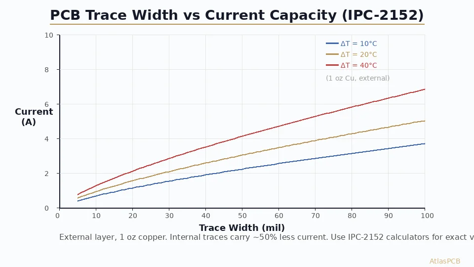
Impedance Sensitivity to Trace Width
For a typical 50 Ω microstrip on FR-4 (Dk = 3.8, 1 oz copper, 4.0 mil dielectric height):
| Trace Width Change | Impedance Change |
|---|---|
| +0.5 mil (+12.7 µm) | -1.5 to -2.0 Ω |
| +1.0 mil (+25.4 µm) | -3.0 to -4.0 Ω |
| -0.5 mil (-12.7 µm) | +1.5 to +2.0 Ω |
| -1.0 mil (-25.4 µm) | +3.0 to +4.5 Ω |
A 1 mil trace width error corresponds to roughly a 3–4 Ω impedance shift on a 50 Ω line—that alone can push the impedance outside the ±10% tolerance window. This illustrates why etch compensation calibration is critical for impedance-controlled designs.
For related discussion on how plating uniformity affects impedance, see [Copper plating thickness uniformity]/blog/pcb-copper-plating-thickness-uniformity/).
Etch Compensation for Fine-Line PCBs
Fine-line PCBs (traces ≤ 3 mil / 75 µm) push etch compensation to its limits. At these dimensions, the undercut becomes a significant fraction of the total trace width, and process tolerances shrink dramatically.
Challenges at Fine Pitch
| Feature Width | ½ oz Undercut (EF 3.0) | Undercut as % of Width | Process Window |
|---|---|---|---|
| 5.0 mil (127 µm) | 11.6 µm total | 9% | Comfortable |
| 4.0 mil (100 µm) | 11.6 µm total | 12% | Manageable |
| 3.0 mil (75 µm) | 11.6 µm total | 15% | Tight |
| 2.0 mil (50 µm) | 11.6 µm total | 23% | Very tight |
| 1.5 mil (38 µm) | 11.6 µm total | 31% | Near limit |
When undercut represents more than 20% of the feature width, process control becomes extremely demanding. Small variations in etch time, temperature, or etchant concentration produce disproportionate width changes.
Strategies for Fine-Line Success
1. Use thinner base copper. The single most effective way to reduce etch compensation is to start with thinner copper. Fine-line designs should use ⅓ oz (12 µm) or ¼ oz (9 µm) base copper on inner layers. The reduced copper thickness directly reduces undercut.
2. Semi-additive process (SAP) or modified semi-additive process (mSAP). Instead of subtractive etching from thick copper, SAP starts with a very thin seed layer (1–3 µm copper), patterns the resist, electroplates copper only where traces are desired, strips resist, and flash-etches the thin seed layer. Because only 1–3 µm of copper is etched away, undercut is negligible (< 1 µm per side). mSAP is the dominant technology for smartphone HDI boards achieving 30/30 µm (1.2/1.2 mil) line/space.
3. Optimize etchant chemistry. Cupric chloride at controlled pH and temperature yields higher etch factors than alkaline ammoniacal for outer layers. Some fabricators use specialized additives to further improve etch factor.
4. Laser direct imaging (LDI). LDI eliminates film registration error, placing the resist pattern directly on the panel with ±5 µm accuracy. This is essential at fine pitch where traditional film-based imaging introduces ±15–25 µm registration error.
5. Statistical process control (SPC). Monitor finished trace widths on every panel using automated measurement. Track Cp and Cpk indices. Target Cpk ≥ 1.33 for controlled processes, ≥ 1.67 for fine-line critical features.
Etch Compensation for Inner vs. Outer Layers
Inner layers and outer layers have different etch compensation requirements because they go through different processing sequences.
Inner Layers
Inner layers are etched using subtractive processing with the base copper foil (no additional plating). The compensation calculation is straightforward:
- Start with laminate copper weight (e.g., ½ oz = 17.5 µm)
- Apply etch factor for your etchant chemistry
- Compensation = Copper thickness / Etch factor
Outer Layers
Outer layers are more complex because additional copper is deposited during electroplating (panel plating and pattern plating) before etching:
- Base copper: ½ oz (17.5 µm) typical
- Electroless copper: 1–3 µm (for PTH hole activation)
- Electrolytic panel plate: 5–8 µm
- Electrolytic pattern plate: 20–25 µm (in trace areas only, under tin resist)
The total copper being etched on outer layers is the base copper + electroless + panel plate = approximately 24–29 µm for ½ oz base. This is significantly more than the 17.5 µm base copper alone, and the compensation must account for the total etched thickness.
| Layer Type | Base Cu | Additional Plating | Total Etch Thickness | Compensation per Side (EF 3.0) |
|---|---|---|---|---|
| Inner (½ oz) | 17.5 µm | 0 | 17.5 µm | 5.8 µm |
| Outer (½ oz base) | 17.5 µm | 7–11 µm | 24.5–28.5 µm | 8.2–9.5 µm |
| Inner (1 oz) | 35 µm | 0 | 35 µm | 11.7 µm |
| Outer (1 oz base) | 35 µm | 7–11 µm | 42–46 µm | 14.0–15.3 µm |
This is why outer layer traces are often wider than inner layer traces in impedance-controlled stackups—even if the target impedance is the same, the greater etch compensation needed for outer layers results in wider artwork features.
DFM Guidelines for Etch Compensation
What the Designer Should Do
Design to finished dimensions. Place traces in your CAD tool at the desired finished width, not the compensated width. Etch compensation is applied by the fabricator during CAM processing—not by the designer. If you pre-compensate and the fabricator also compensates, your traces will be oversized.
Specify copper weights clearly. Annotate your stackup table and fab drawing with exact copper weights for each layer. The fabricator calculates compensation based on these values.
Call out impedance requirements on the fab drawing. Specify target impedance, tolerance (typically ±10%), and reference the specific traces or net classes. The fabricator will adjust compensation to hit the impedance target, which may differ from the nominal compensation for non-impedance traces.
Avoid minimum feature sizes at heavy copper. If using 2 oz copper, do not design 3 mil traces. The undercut at 2 oz (~23–28 µm per side) would consume a huge fraction of a 75 µm trace. Maintain a minimum trace width of at least 2× the total undercut.
Recommended minimum trace widths by copper weight:
| Copper Weight | Total Undercut (EF 3.0) | Minimum Trace Width | Minimum Space |
|---|---|---|---|
| ⅓ oz | 8 µm | 2.0 mil (50 µm) | 2.0 mil (50 µm) |
| ½ oz | 12 µm | 3.0 mil (75 µm) | 3.0 mil (75 µm) |
| 1 oz | 23 µm | 4.0 mil (100 µm) | 4.0 mil (100 µm) |
| 2 oz | 47 µm | 6.0 mil (150 µm) | 6.0 mil (150 µm) |
| 3 oz | 70 µm | 8.0 mil (200 µm) | 8.0 mil (200 µm) |
What the Fabricator Does
The fabricator’s CAM department applies etch compensation as part of tooling preparation:
- Measure etch factor — Run test coupons with the current chemistry and equipment to establish the actual etch factor
- Calculate compensation — Apply the compensation formula per layer based on copper weight and measured etch factor
- Adjust artwork — Widen all traces, pads, and copper features by the compensation amount using CAM software (Genesis, InCAM, etc.)
- Verify impedance — For controlled impedance traces, simulate the compensated trace width with the trapezoidal model and iterate until the impedance target is met
- Monitor in production — Measure finished trace widths on production panels and adjust compensation if process drift is detected
Advanced Topic: Differential Etch Compensation
In some designs, different features on the same layer may require different compensation amounts:
- Isolated traces vs. dense arrays — Etchant pooling between closely spaced traces can cause uneven etch rates. Dense trace arrays may need slightly less compensation than isolated traces on the same panel.
- Large copper pours vs. narrow traces — Wide copper areas etch slower at the edges than narrow traces. Some fabricators apply differential compensation to maintain uniform width across varying feature geometries.
- Pad vs. trace compensation — Pads (especially BGA pads) may receive different compensation than traces to maintain correct pad diameter after etching.
This differential compensation is typically handled by the fabricator’s CAM tools, which can apply feature-dependent compensation rules. As a designer, you should communicate your critical features and tolerances so the fabricator can prioritize accordingly.
Measuring and Verifying Etch Compensation Results
Cross-Section Analysis
The definitive measurement of etch compensation effectiveness is a microsection (cross-section) of the finished trace. This reveals:
- Top width and bottom width of the trapezoidal profile
- Copper thickness
- Sidewall angle (from which etch factor can be back-calculated)
- Undercut distance under the resist line
Request cross-sections on first articles for impedance-critical layers. Specify measurement at multiple locations across the panel to catch any edge-to-center etch variation.
Coupon-Based Monitoring
IPC impedance test coupons (IPC-2141) include trace width measurement pads that allow non-destructive width measurement using optical or resistive methods. These coupons should be included on every production panel for statistical monitoring.
Automated Optical Inspection (AOI)
Modern AOI systems measure trace widths across the entire panel surface with ±2 µm resolution. AOI data provides a full-panel trace width map, revealing any systematic etch variation (center-to-edge, leading-edge-to-trailing-edge, top-spray vs. bottom-spray asymmetry).
Common Etch Compensation Errors
Error 1: Designer Pre-Compensates Artwork
If the designer adds etch compensation in the CAD tool and the fabricator adds compensation again during CAM processing, every trace will be oversized. Always design to finished dimensions and let the fabricator handle compensation.
Error 2: Wrong Copper Weight Assumption
If the designer specifies 1 oz copper but the fabricator uses ½ oz base + panel plating, the total etch thickness differs from the assumption. Communicate the full copper buildup (base + plating) for each layer.
Error 3: Single Compensation for All Layers
Inner layers and outer layers require different compensation (as discussed above). Applying a single compensation value across all layers results in incorrect widths on at least one layer type.
Error 4: Ignoring Plating Thickness Variation
Electroplated copper thickness varies across the panel (thicker at edges, thinner at center due to current density distribution). This variation means the effective etch depth varies, requiring the etch compensation to be calibrated for the average case with enough margin for the extremes.
For a full exploration of how plating distribution affects your board, see [Copper plating thickness uniformity]/blog/pcb-copper-plating-thickness-uniformity/).
Error 5: Not Accounting for Etch Factor Drift
Etch factor is not constant—it drifts as etchant concentration, temperature, and equipment condition change. Fabricators must monitor and recalibrate etch factor regularly. Designers should spec reasonable trace width tolerances (±0.5 mil for standard, ±0.25 mil for fine-line) rather than zero-tolerance expectations.
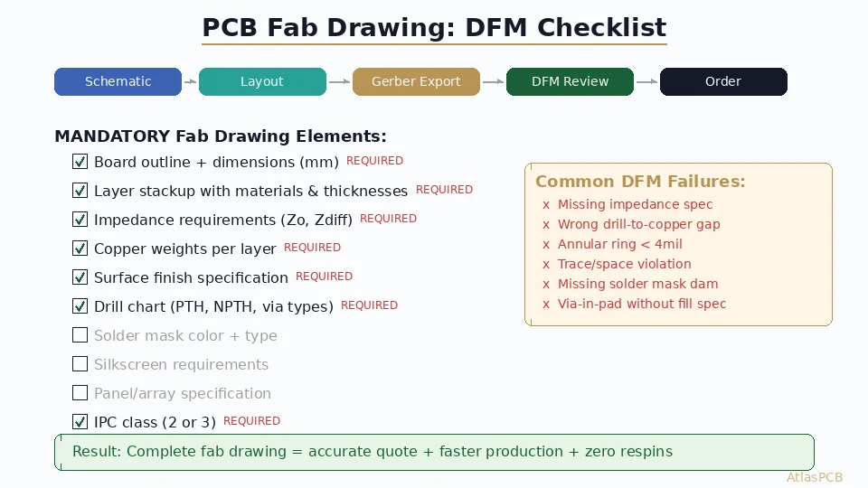
Etch Compensation in the Context of DFM
Etch compensation is one component of a broader DFM (Design for Manufacturability) strategy. Related DFM considerations include:
- Copper balance — Uneven copper distribution causes uneven etch rates across the panel. Add copper thieving or balance patterns to equalize the copper density.
- Annular ring — Pad diameters after etch compensation must still provide adequate annular ring around drilled holes.
- Solder mask registration — The compensated trace position must align with solder mask openings; registration tolerances stack.
- Impedance stackup design — Dielectric thickness and copper weight choices should consider the etch compensation impact from the start.
For a comprehensive pre-fabrication review, see our [PCB DFM checklist]/blog/pcb-dfm-checklist/).
Conclusion and Next Steps
Etch compensation is the invisible bridge between your design intent and the physical board. Understanding how copper weight, etch factor, and layer type influence trace width loss allows you to design with realistic expectations, communicate effectively with your fabricator, and achieve consistent impedance and geometry in production.
Key takeaways:
- Design to finished dimensions—let the fabricator compensate
- Thinner copper enables finer features with less compensation
- Inner and outer layers require different compensation values
- Trapezoidal trace models are essential for accurate impedance prediction
- Monitor etch factor and trace width with statistical process control
Ready to validate your trace width and impedance specifications? Upload your Gerbers for a free engineering review and our DFM team will verify compensation compatibility, check minimum feature sizes against your copper weight, and confirm impedance targets are achievable before production.
Further Reading
- [PCB Manufacturer with Engineering Review: Why Human DFM Audit Matters]/blog/pcb-manufacturer-engineering-review/)
- [PCB Panelization and Array Design: V-Score vs Tab Routing, DFM Rules, and Cost Optimization]/blog/pcb-panelization-v-score-tab-routing-dfm-cost-optimization/)
- [Rogers PCB Fabrication: Material Sourcing, Lead Times & Quality Control]/blog/rogers-pcb-fabrication/)
- [阻焊坝设计 — 规则、公差与DFM最佳实践]/blog/pcb-solder-mask-dam-design-rules-dfm/)
- [Aluminum PCB Thermal Design for High-Power LED and Motor Drivers: Material Selection, Stackup, and DFM Guide]/blog/aluminum-pcb-thermal-design-led-motor-driver/)
- Material Options & Capabilities
About AtlasPCB — We specialize in complex PCB manufacturing for HDI, RF, and high-reliability applications. Explore our free engineering DFM review . Every order includes free engineering review. Get your quote.
Reviewed by AtlasPCB Engineering Team — IPC-certified manufacturing specialists with 15+ years of production experience in HDI, RF, and high-reliability PCB fabrication. Content based on factory floor data and real customer design reviews.
- etch-compensation
- trace-width
- fine-line
- pcb-manufacturing
- dfm