· AtlasPCB Engineering · Engineering · 6 min read
Conformal Coating for PCBs: Types, Application Methods, and IPC-CC-830 Compliance
Complete guide to PCB conformal coating materials (acrylic, silicone, polyurethane, parylene, epoxy), application methods (spray, dip, selective), thickness requirements, and IPC-CC-830 qualification testing for harsh environment protection.
Why PCBs Need Conformal Coating
Electronics deployed outside the controlled environment of a server room face relentless attack from moisture, salt spray, dust, fungal growth, and chemical vapors. Conformal coating creates an invisible barrier that extends PCB life from months to decades in harsh conditions.
The global conformal coating market exceeds $14 billion (2025), driven by automotive electrification, industrial IoT deployments, and aerospace miniaturization. Every automotive ECU, every outdoor sensor node, and every medical implant relies on some form of protective coating.
This guide covers the engineering decisions behind coating selection: material chemistry, application methods, design-for-coating rules, and qualification testing.
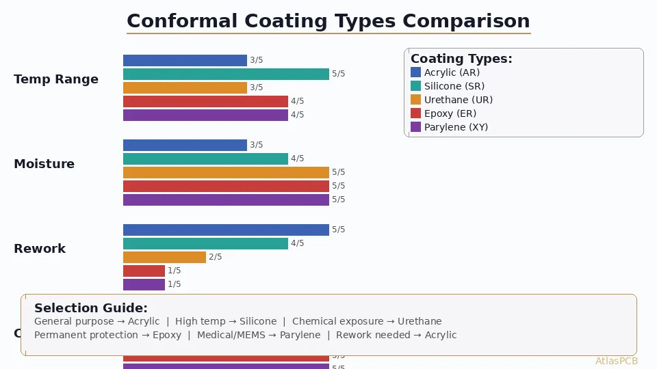
The Five Coating Chemistries
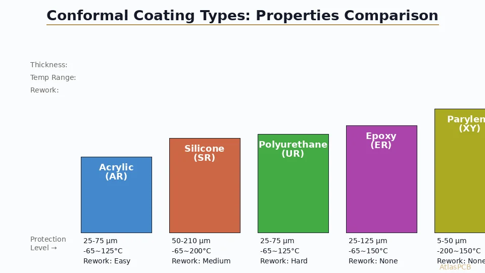
Acrylic Resin (Type AR)
Characteristics:
- Thickness: 25-75 µm typical
- Temperature range: -65°C to +125°C
- Dielectric strength: 50-100 V/µm
- Cure method: Solvent evaporation (room temperature) or UV
Strengths:
- Excellent moisture resistance for the cost
- Easy application and fast drying (<30 min)
- Fully reworkable with IPA or acetone
- Good optical clarity (UV inspection friendly)
- Low stress on components during cure
Weaknesses:
- Poor chemical/solvent resistance (dissolves in many solvents)
- Limited high-temperature performance
- No abrasion resistance
- Susceptible to fungal attack in tropical environments
Best for: Consumer electronics, indoor industrial equipment, products requiring field serviceability.
Silicone Resin (Type SR)
Characteristics:
- Thickness: 50-210 µm typical
- Temperature range: -65°C to +200°C
- Dielectric strength: 20-25 V/µm
- Cure method: Moisture cure (RTV) or heat cure (1-component)
Strengths:
- Widest operating temperature range
- Excellent flexibility — absorbs CTE mismatch stress
- Superior moisture resistance
- Chemical inertness
- Vibration damping properties
Weaknesses:
- Expensive (2-3× acrylic cost)
- Poor abrasion resistance
- Difficult to achieve thin, uniform films
- Long cure times (24 h for RTV)
- Low adhesion — may require primer on some surfaces
Best for: Automotive underhood, aerospace, LED lighting, power electronics with extreme thermal cycling.
Polyurethane Resin (Type UR)
Characteristics:
- Thickness: 25-75 µm typical
- Temperature range: -65°C to +125°C
- Dielectric strength: 50-100 V/µm
- Cure method: Moisture cure or 2-component mix
Strengths:
- Excellent chemical and solvent resistance
- Good abrasion and mechanical protection
- Strong humidity resistance
- Reasonable cost
Weaknesses:
- Difficult/impossible to rework (chemical removal damages components)
- Shrinks during cure (stress on fine-pitch components)
- Yellows under UV exposure
- Pot life limitations for 2-component systems
Best for: Industrial controls, marine electronics, chemical processing environments where rework is unlikely.
Epoxy Resin (Type ER)
Characteristics:
- Thickness: 25-125 µm typical
- Temperature range: -65°C to +150°C
- Dielectric strength: 80-120 V/µm
- Cure method: Heat cure (typically 80-150°C)
Strengths:
- Hardest, most abrasion-resistant coating
- Excellent chemical resistance
- Superior humidity barrier
- High dielectric strength
Weaknesses:
- Virtually non-reworkable
- Rigid — high stress during thermal cycling
- Can crack under thermal shock
- Limited flexibility for flex or vibrating assemblies
- Heat cure may stress temperature-sensitive components
Best for: Military/defense electronics where permanence is acceptable, potted assemblies, high-voltage applications.
Parylene (Type XY)
Characteristics:
- Thickness: 5-50 µm typical
- Temperature range: -200°C to +150°C (Type C)
- Dielectric strength: 220 V/µm
- Cure method: Vapor deposition (CVD) at room temperature
Strengths:
- Pinhole-free at <10 µm — no other coating achieves this
- Penetrates under components and into tight spaces
- Zero stress during deposition (room temperature process)
- Biocompatible (FDA approved for implants)
- Best moisture barrier per unit thickness
Weaknesses:
- Very expensive ($500-2000+ per batch)
- Requires vacuum deposition equipment
- Cannot be selectively applied without masking
- Extremely difficult to rework (plasma or micro-abrasion)
- Batch process — not suitable for inline production
Best for: Medical implants, MEMS devices, aerospace sensors, military avionics where ultimate protection justifies cost.
Application Methods
Spray Coating (Manual and Automated)
The most common method for production volumes:
- Manual spray: Operator uses HVLP gun, suitable for prototypes and low volume
- Automated spray: Robotic arm with programmed paths, ±10 µm thickness control
- Coverage: Good for flat boards, poor penetration under tall components
- Speed: 30-60 seconds per board (automated)
- Waste: 30-50% overspray (higher for manual)
Selective Coating (Needle Valve / Film Coating)
Precision application that avoids connectors and keep-out zones:
- Method: Programmable nozzle deposits coating exactly where needed
- Advantages: No masking required, minimal waste, high repeatability
- Resolution: 0.5 mm edge definition
- Speed: 60-180 seconds per board depending on complexity
- Cost: Higher equipment cost but lower material waste and labor
PCB Assembly with Conformal Coating?
AtlasPCB offers selective conformal coating services with IPC-CC-830 qualified materials. From prototype to production.
Get a Quote →Dip Coating
Full immersion for complete coverage:
- Method: Board lowered into coating tank, withdrawn at controlled speed
- Advantages: Excellent coverage including under components, simple equipment
- Disadvantages: Requires extensive masking, difficult thickness control
- Typical use: High-reliability aerospace/defense where 100% coverage is mandatory
- Withdrawal speed: 1-5 mm/s controls final thickness
Vapor Deposition (Parylene Only)
Unique process producing the highest-quality conformal coating:
- Parylene dimer granules loaded into vaporizer
- Heated to 150°C → sublimation to dimer gas
- Pyrolysis at 690°C → monomer gas
- Deposition at room temperature → polymerization on all exposed surfaces
- Chamber pressure: 20-50 mTorr
The room-temperature deposition means zero thermal stress on the assembly.
Design for Coating (DFC) Rules
Keep-Out Areas (Must Not Coat)
- Connectors and test points
- Switches, potentiometers, adjustment components
- Heat sinks and thermal interface surfaces
- LEDs (unless optically transparent coating confirmed)
- Batteries and battery contacts
- Grounding points and mounting hardware
Design Accommodations
- Component spacing: Minimum 2 mm clearance around keep-out components for masking
- Connector orientation: Face board edge for easier masking/boot installation
- Fiducial marks: Keep visible for AOI inspection post-coating
- Test points: Group together for efficient masking
- Coating dam: Add solder mask dam (0.5 mm raised feature) around sensitive areas
Thickness Verification Zones
Designate 3-5 flat areas on the board (away from components) as thickness measurement zones. These should be:
- ≥5 mm × 5 mm flat copper area
- Accessible to eddy-current or magnetic gauge probes
- Located at board center, corners, and mid-edges to verify uniformity
IPC-CC-830 Qualification Testing
IPC-CC-830B “Qualification and Performance of Electrical Insulating Compound for Printed Board Assemblies” defines the testing protocol:
Required Tests
| Test | Method | Pass Criteria |
|---|---|---|
| Insulation Resistance | 96h at 65°C/90% RH, 100V DC | >100 MΩ after conditioning |
| Dielectric Withstanding | Per IPC-TM-650 2.6.3 | No breakdown at rated voltage |
| Thermal Shock | -65°C to +125°C, 100 cycles | No cracking, delamination, or loss of adhesion |
| Moisture Resistance | 10 days at 65°C/90% RH | <10× resistance change |
| Fungus Resistance | 28 days MIL-STD-810 Method 508 | No growth support |
| Flexibility | Mandrel bend test | No cracking at specified radius |
| Flammability | UL 94 V-0 or V-1 | Self-extinguishing |
| UV Fluorescence | 365 nm blacklight inspection | Coating visible for coverage verification |
Production Quality Control
- Visual inspection: UV fluorescence check for coverage gaps (acrylic and UR)
- Thickness measurement: Eddy-current gauge on designated zones
- Adhesion test: Cross-hatch tape test per ASTM D3359 (sampled)
- SIR monitoring: Surface insulation resistance coupons processed with production boards
Coating Selection Decision Matrix
| Requirement | Best Choice |
|---|---|
| Field reworkable | Acrylic (AR) |
| High temperature (>150°C) | Silicone (SR) |
| Chemical exposure | Polyurethane (UR) or Epoxy (ER) |
| Biocompatible/medical | Parylene (XY) |
| Lowest cost | Acrylic (AR) |
| Thinnest protection | Parylene (XY) |
| Highest volume production | Acrylic (AR) spray |
| 100% coverage required | Parylene (XY) or Dip |
| Thermal cycling >1000 cycles | Silicone (SR) |
| Outdoor UV exposure | Silicone (SR) |
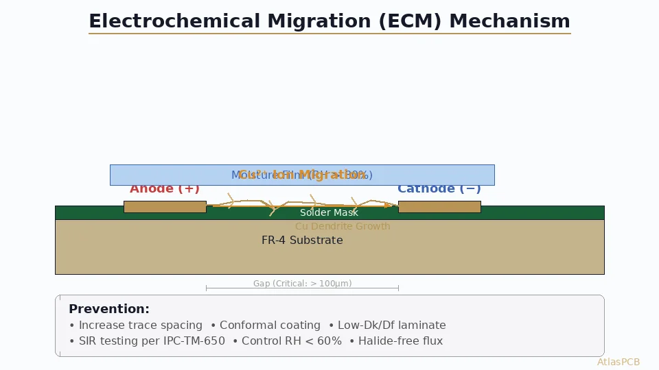
Common Failures and Prevention
Dewetting
Cause: Contamination (flux residue, oils, silicone) preventing coating adhesion. Prevention: IPC-compliant cleaning (IPA + DI water) before coating. Verify surface energy >38 dyne/cm.
Orange Peel Texture
Cause: Spray viscosity too high or spray distance too far. Prevention: Maintain 15-25 cm spray distance, verify viscosity per TDS specification.
Bubbles and Pinholes
Cause: Outgassing from flux residue, trapped air under components, coating applied too thick. Prevention: Proper cleaning, controlled thickness (multiple thin coats vs. one thick coat), adequate flash time between coats.
Cracking at Thermal Cycle
Cause: Rigid coating (epoxy/UR) on flexible assembly or large temperature range. Prevention: Switch to silicone for high ΔT applications, reduce coating thickness, or use more flexible formulation.
Industry Trends (2026)
- UV-LED curable coatings — Replacing mercury-vapor UV with energy-efficient LED cure
- Nano-composite coatings — Silica nanoparticles improving abrasion resistance without sacrificing flexibility
- Automated inspection — AI-powered AOI detecting coating defects under UV at line speed
- Low-VOC formulations — Regulatory pressure driving water-based and 100% solids systems
- Selective parylene — Laser-mask parylene for partial coverage without physical masking
Further Reading
- PCB Surface Finish Selection Guide: ENIG, OSP, and Hard Gold
- What Causes PCB Delamination
- IPC-6012 ES Class: Automotive and Aerospace PCB Reliability
- DFM for Fine-Pitch BGA PCB Design
Need conformal-coated PCB assemblies for harsh environments? AtlasPCB provides complete turnkey solutions from bare board fabrication through coating and final inspection. Our IPC-CC-830 qualified processes ensure reliable protection in automotive, industrial, and aerospace applications. Request a quote or learn about our assembly services.
About AtlasPCB — We specialize in complex PCB manufacturing for HDI, RF, and high-reliability applications. Explore our full PCB manufacturing capabilities . Every order includes free engineering review. Get your quote.
Reviewed by AtlasPCB Engineering Team — IPC-certified manufacturing specialists with 15+ years of production experience in HDI, RF, and high-reliability PCB fabrication. Content based on factory floor data and real customer design reviews.
- conformal coating
- PCB protection
- IPC-CC-830
- harsh environment
- moisture resistance
- parylene
- acrylic coating