· AtlasPCB Engineering · Engineering · 9 min read
BGA Rework and Reballing: Complete Process Guide for High-Reliability PCBs
Master BGA rework and reballing techniques for high-reliability PCB assemblies. Learn proper thermal profiling, flux selection, pad preparation, and IPC-7095 compliance for aerospace, medical, and automotive applications.
Introduction: Why BGA Rework Matters
Ball Grid Array (BGA) packages dominate modern electronics—from smartphone processors to FPGA arrays in aerospace systems. When a BGA fails or requires replacement during prototype debugging, rework becomes essential. Unlike through-hole or QFP components that can be hand-soldered, BGA rework demands specialized equipment, precise thermal control, and rigorous process validation.
The stakes are high. A botched BGA rework can damage adjacent components, lift pads, crack the PCB substrate, or create hidden solder defects that pass visual inspection but fail in the field. For [IPC Class 3 applications]/blog/ipc-a-600-class-2-vs-class-3-pcb-acceptability-en/)—aerospace, medical devices, and military systems—the consequences of poor rework can be catastrophic.
This guide covers the complete BGA rework and reballing process, from equipment selection through validation, with practical techniques that ensure high first-pass yield and long-term reliability.
Understanding BGA Failure Modes
Before reworking a BGA, understanding why it failed guides the repair strategy:
Common BGA Failure Mechanisms
Solder joint failures:
- Head-in-pillow (HiP) defects from warpage during reflow
- Cold joints from insufficient peak temperature
- Tin whisker growth in pure tin finishes
- Electromigration at high current density joints
Package-level failures:
- Die delamination from moisture absorption (popcorn effect)
- Wire bond fracture from thermal cycling
- Underfill cracking in flip-chip BGAs
- Substrate warpage exceeding coplanarity limits
PCB-related failures:
- Pad cratering (resin fracture beneath pad)
- Via-in-pad voiding causing intermittent opens
- Copper dissolution from excessive rework cycles
- CAF (Conductive Anodic Filament) growth between vias
Diagnostic Tools
Before removing a BGA, diagnosis confirms it’s actually the failure source:
- X-ray inspection: Reveals solder voids, bridging, head-in-pillow defects
- Thermal imaging: Identifies hot spots indicating short circuits
- Boundary scan (JTAG): Tests interconnect integrity without physical access
- Time-domain reflectometry: Locates opens/shorts in BGA signal paths
- Dye-and-pry: Destructive analysis of solder joint fracture surfaces
BGA Rework Equipment
Rework Station Selection
Professional BGA rework requires purpose-built stations. Key specifications:
| Feature | Entry Level | Professional | High-Reliability |
|---|---|---|---|
| Heating method | IR lamp | Focused IR + convection | Split-vision convection |
| Temperature control | ±5°C | ±2°C | ±1°C |
| Placement accuracy | ±100μm | ±50μm | ±25μm |
| Vision system | Top-only | Split prism | Split + side view |
| Profile channels | 2-4 | 8-12 | 16+ |
| Max component size | 35×35mm | 50×50mm | 75×75mm |
| Bottom heater | IR panel | Multi-zone IR | Programmable zone |
Recommended stations for high-reliability work:
- Ersa HR 600/2 (split-optic, ±25μm accuracy)
- Finetech FINEPLACER sigma (sub-micron for advanced packaging)
- Kurtz Ersa VOIDLESS (integrated vacuum for void reduction)
Essential Accessories
- Nozzles: Component-specific, must match BGA package outline within 1-2mm
- Thermocouples: K-type, 0.1mm diameter for profile validation
- Flux dispensing: Pneumatic dispenser with 22-25 gauge needles
- Solder paste stencils: Mini-stencils (50-100mm frame) for site replenishment
- BGA reballing stencils: Precision laser-cut, thickness matched to ball diameter
- Cleaning equipment: Ultrasonic bath with appropriate solvents
The BGA Removal Process
Step 1: Pre-Rework Preparation
Board assessment:
- Document all adjacent component positions (photograph with scale reference)
- Verify board flatness (warpage <0.75% of diagonal per IPC-A-610)
- Check moisture sensitivity level (MSL) — bake if >MSL-3 and exposed >168 hours
- Mask adjacent heat-sensitive components with Kapton tape and aluminum shields
Flux application:
- Apply low-residue, no-clean flux around the BGA perimeter
- Flux penetrates under the component during heating, reducing surface tension
- For underfilled BGAs: apply underfill remover (proprietary chemistry) 24h before rework
Step 2: Thermal Profiling
Proper thermal profiling is the single most critical factor in BGA rework success.
Profile development procedure:
- Attach thermocouples to: top of BGA body, PCB surface adjacent to BGA, nearest sensitive component, bottom board surface
- Run profile at 70% of target parameters to validate uniformity
- Adjust zone temperatures until delta-T across BGA is <10°C
- Record successful profile for repeatability
Critical profile parameters (SAC305):
Preheat/Soak: 150-200°C for 60-120 seconds
Ramp rate: 1-3°C/second (max)
Time above liquidus (TAL): 30-90 seconds
Peak temperature: 235-250°C (component body)
Cooling rate: 2-4°C/second (max, to prevent thermal shock)
Bottom heater: 100-150°C (reduces thermal gradient)
Step 3: Component Removal
- Start bottom preheater — bring board to 100-150°C uniformly
- Begin top heater profile — follow validated thermal profile
- Monitor thermocouples — verify all zones are tracking within specification
- At peak temperature, apply gentle upward force with vacuum nozzle
- Component lifts when all joints reach liquidus — do NOT force removal
- Immediately move to cooling — controlled rate prevents PCB warpage
Critical warnings:
- Never twist or slide the BGA during removal (damages pads)
- If component doesn’t release at peak temp, check for underfill or mechanical fasteners
- Extended time above liquidus degrades copper pads — maximum 90 seconds TAL
Step 4: Site Preparation
After BGA removal, the PCB site requires careful preparation:
Residual solder removal:
- Apply fresh flux to the pad array
- Use copper braid (desoldering wick) with temperature-controlled iron
- Work from center outward to avoid pulling pads
- Alternative: automated solder removal tools (Pace SX-100, Metcal)
Pad inspection (critical checkpoint):
- 100% visual inspection under 10-20× magnification
- Check for: pad lifting, solder mask damage, exposed copper, cratering
- Measure pad diameter — must be within ±10% of design specification
- Use continuity test on sample pads to verify trace connection
Solder replenishment:
- For NSMD (non-solder-mask-defined) pads: mini-stencil printing of solder paste
- For SMD (solder-mask-defined) pads: flux-only may suffice if original solder height is adequate
- Alternatively: dip the replacement BGA in flux (no paste on pads)
Need Expert BGA Rework Support?
AtlasPCB offers IPC-7711/7721 certified rework services for BGA, μBGA, and CSP packages on boards up to 40 layers. Our split-vision stations achieve ±25μm placement accuracy.
Get Rework Quote →BGA Reballing Process
Reballing restores solder spheres on a removed BGA component for reuse. This is common during:
- Prototype debugging (replacing known-good components on new revisions)
- Component salvage from end-of-life boards
- Failure analysis (removing and re-inspecting suspect parts)
Reballing Methods
Stencil-based reballing (most common):
- Clean all residual solder from BGA substrate pads
- Apply thin layer of tacky flux to pads
- Align precision reballing stencil over the BGA
- Place solder spheres into stencil apertures (manual or automated)
- Remove excess spheres with squeegee
- Lift stencil carefully
- Reflow using proper profile to attach spheres
Preform-based reballing:
- Use pre-made solder sphere arrays on carrier tape
- Align carrier to BGA using optical reference marks
- Transfer spheres simultaneously
- Reflow to attach
Laser-assisted reballing (advanced):
- Individual sphere placement using laser-guided system
- Each sphere reflowed immediately after placement
- Best for mixed-pitch or non-standard arrays
- Highest accuracy but slowest throughput
Sphere Selection
Solder sphere specifications must match original BGA design:
| BGA Pitch | Sphere Diameter | Diameter Tolerance | Material |
|---|---|---|---|
| 1.27mm | 0.76mm (30mil) | ±30μm | SAC305 |
| 1.0mm | 0.60mm (24mil) | ±25μm | SAC305 |
| 0.8mm | 0.45mm (18mil) | ±20μm | SAC305 |
| 0.65mm | 0.35mm (14mil) | ±15μm | SAC305 |
| 0.5mm | 0.30mm (12mil) | ±12μm | SAC305 |
| 0.4mm | 0.25mm (10mil) | ±10μm | SAC305/SnAg |
Post-Reballing Validation
Before reinstalling a reballed BGA:
- Coplanarity measurement: All balls within 100μm of reference plane
- X-ray inspection: No voids >25% of ball volume, no missing balls
- Ball shear test (sample): >200g force for 0.5mm pitch, per JESD22-B117
- Visual inspection: Uniform sphere shape, no bridging, proper wetting
Replacement BGA Installation
Placement Procedure
- Apply flux to either the PCB pads or BGA spheres (not both — excess flux traps volatiles)
- Align BGA using split-vision optics:
- Match package fiducials to PCB fiducials
- Verify X, Y, and theta (rotation) alignment
- Confirm correct orientation (pin 1 indicator)
- Lower component onto pads — spheres should contact paste/flux
- Verify alignment through prism view before releasing vacuum
- Begin reflow profile immediately after placement
Reflow Profile for Installation
The installation profile differs slightly from removal:
Preheat: 25°C → 150°C at 1.5°C/s
Soak: 150-200°C for 60-90 seconds
Ramp to peak: 200°C → 245°C at 2°C/s
Peak: 240-245°C for 20-40 seconds
Time above liquidus: 45-75 seconds
Cooling: 245°C → 200°C at 3°C/s max
Key differences from removal:
- Slightly lower peak temperature (less thermal stress since joints must form, not release)
- Shorter TAL (less opportunity for intermetallic growth)
- More aggressive cooling (forms finer grain structure, better fatigue life)
Self-Alignment Effect
During reflow, surface tension of molten solder pulls the BGA into alignment with the pads. This self-alignment effect can correct up to 50% of ball pitch misalignment (e.g., ±0.2mm on 0.8mm pitch). However, relying on self-alignment is poor practice for high-reliability work — always achieve <50μm placement accuracy before reflow.
Post-Rework Inspection
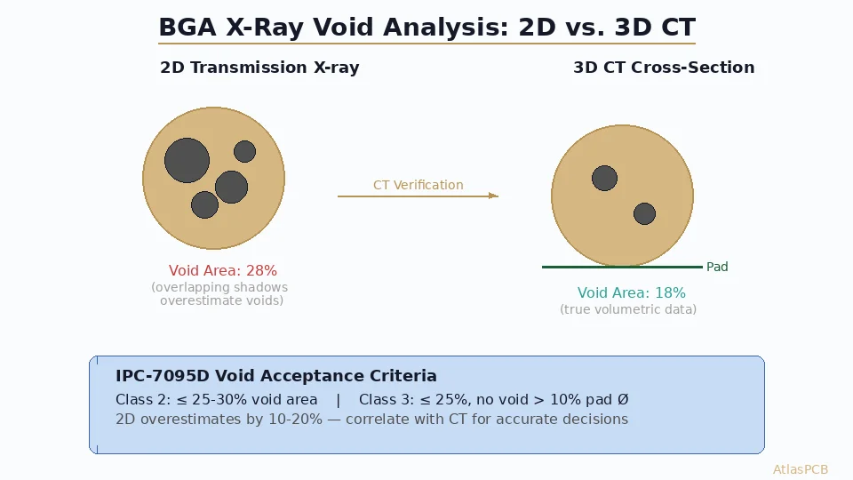
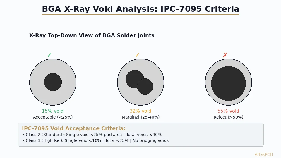
Mandatory Inspections (IPC-7095D)
X-ray inspection (100% of reworked joints):
- Verify solder joint formation on all balls
- Check for voiding (reject if >25% of joint volume)
- Confirm no bridging between adjacent balls
- Verify no head-in-pillow defects
Automated optical inspection:
- Peripheral solder joints visible at component edges
- Solder mask integrity around rework site
- No flux residue bridging between pads (if no-clean flux used)
Cross-section analysis (on qualification coupons):
- Intermetallic compound (IMC) thickness: 1-4μm target
- No pad cratering or resin fracture
- Via barrel integrity in via-in-pad structures
- Copper dissolution not exceeding 25% of original pad thickness
Functional Validation
After physical inspection passes:
- Boundary scan test: Verify all BGA I/O connections
- Signal integrity measurement: Compare to pre-rework baseline if available
- Thermal cycling qualification: -40°C to +125°C for Class 3 applications
- Vibration testing: If assembly will experience shock/vibration loads
Common BGA Rework Defects and Solutions
Head-in-Pillow (HiP) Defects
Cause: BGA warpage during reflow causes ball to separate from paste at peak temperature, then reconnect during cooling with oxide layer trapped between.
Prevention:
- Use vacuum-assisted reflow (reduces voiding and warpage)
- Optimize soak profile to equalize package temperature
- Apply flux to both surfaces for oxide reduction
- Consider [controlled atmosphere reflow]/blog/pcb-copper-plating-thickness-uniformity/) (nitrogen)
Pad Cratering
Cause: Mechanical stress during removal fractures the resin beneath the copper pad.
Prevention:
- Never apply lateral force during BGA removal
- Ensure ALL joints are fully molten before lifting
- Use copper-defined pads (larger than solder mask opening) for better adhesion
- Specify high-peel-strength laminate (≥1.0 N/mm per IPC-4101)
Solder Balling
Cause: Flux spattering during reflow creates tiny solder spheres around the BGA perimeter.
Prevention:
- Proper flux volume control (thin film, not pooled)
- Adequate soak profile (flux volatiles escape before peak)
- Use low-spatter flux formulations designed for rework
- Shield adjacent components to capture any ejecta
Incomplete Wetting
Cause: Oxidized pads, insufficient flux activity, or inadequate peak temperature.
Prevention:
- Thorough pad cleaning after solder removal (isopropyl alcohol + brush)
- Fresh flux application immediately before placement
- Verify peak temperature reaches 235°C minimum at joint interface
- Consider more aggressive flux (water-soluble) if compatible with cleaning process
IPC-7095 Compliance Checklist
For [high-reliability applications]/blog/medical-pcb-manufacturing-requirements/), maintain documentation per IPC-7095D:
Pre-rework documentation:
- Failure analysis report justifying rework
- Thermal profile development record
- Operator qualification verification (IPC-7711/7721 certified)
- ESD protection verification
Process documentation:
- Thermal profile printout for each rework cycle
- Thermocouple placement photographs
- Flux type, lot number, and expiration date
- Solder sphere specifications and traceability
Post-rework documentation:
- X-ray images (stored digitally with part serial number)
- Inspection reports per acceptance criteria
- Functional test results
- Thermal cycling test results (if applicable)
When NOT to Rework
Sometimes rework is inadvisable:
- Board has exceeded rework cycle limit (typically 3-5 cycles for standard FR-4)
- Pad damage is present after initial removal — consider wire bond repair instead
- Component is moisture-sensitive and cannot be properly baked
- Board value is less than rework cost — scrapping may be more economical
- Application prohibits rework — some military/space programs require virgin assemblies
- Underfilled BGAs — underfill removal risks substrate damage; replacement PCB is preferred
Conclusion and Best Practices Summary
Successful BGA rework requires treating each step as a controlled process, not an art form. Key takeaways:
- Profile first: Never attempt rework without a validated thermal profile
- Inspect aggressively: 100% X-ray after every BGA rework
- Document everything: Traceability from failure analysis through functional test
- Know your limits: Pad damage, excessive cycles, or inappropriate applications mean stop
- Train continuously: IPC-7711/7721 certification ensures operator competency
For high-reliability PCB assemblies requiring BGA rework, the investment in proper equipment and trained personnel pays dividends in yield, reliability, and customer confidence.
Ready to discuss your BGA rework requirements? AtlasPCB’s IPC-certified team handles BGA rework for applications from prototyping through Class 3 production. Get a quote for expert rework services with full traceability documentation.
Further Reading
- [PCB Rigid-Flex Bend Zone Reliability: Design Rules, Material Selection & Lifecycle Testing]/blog/pcb-rigid-flex-bend-zone-reliability/)
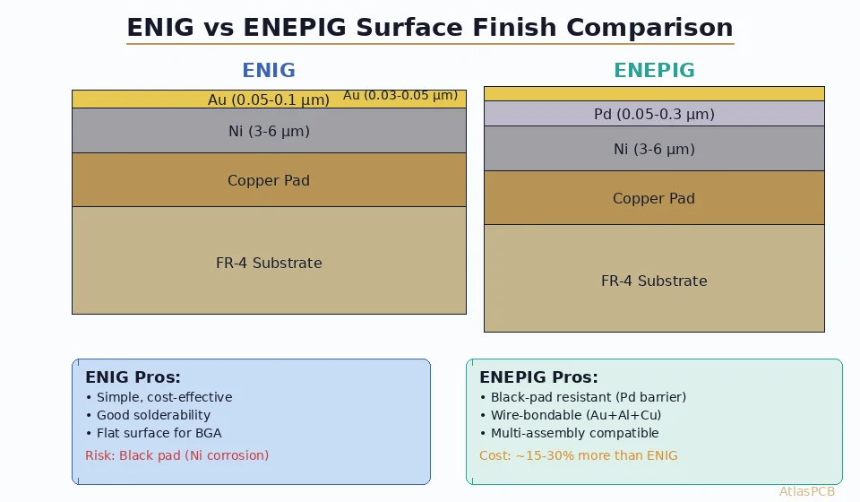
- [ENEPIG vs ENIG Surface Finish: Complete Comparison for Wire Bonding, Solderability, and Long-Term Reliability]/blog/enepig-vs-enig-surface-finish-wire-bonding/)
- [PCB Surface Finish Comparison: OSP vs HASL vs Immersion Silver vs ENIG for Assembly Reliability]/blog/pcb-surface-finish-osp-hasl-enig-immersion-silver-comparison/)
- [PCB Electrical Testing: Flying Probe vs Bed-of-Nails Fixture Testing Compared]/blog/pcb-electrical-testing-flying-probe-vs-fixture/)
- [Medical PCB Manufacturing: FDA Compliance, Traceability & Reliability]/blog/medical-pcb-manufacturing-requirements/)
- Our Manufacturing Capabilities
About AtlasPCB — We specialize in complex PCB manufacturing for HDI, RF, and high-reliability applications. Explore our HDI PCB manufacturing capabilities, PCB assembly services, or get an full PCB manufacturing capabilities . Every order includes free engineering review. Get your quote.
Reviewed by AtlasPCB Engineering Team — IPC-certified manufacturing specialists with 15+ years of production experience in HDI, RF, and high-reliability PCB fabrication. Content based on factory floor data and real customer design reviews.
- BGA
- rework
- reballing
- PCB assembly
- IPC-7095
- high reliability
- soldering