· AtlasPCB Engineering · Engineering · 9 min read
Aluminum PCB vs FR-4: When Metal-Core Makes Sense for Thermal Management
Compare aluminum MCPCB and standard FR-4 for LED, power electronics, and motor driver applications. Thermal conductivity data, cost trade-offs, and design rules for choosing the right substrate.
Quick Decision: Aluminum MCPCB or FR-4?
| Criterion | FR-4 Preferred | Aluminum MCPCB Required |
|---|---|---|
| Power density | < 1 W/cm2 | > 2 W/cm2 |
| Layer count needed | 4+ layers | 1-2 layers |
| Operating voltage | Any | < 500V (dielectric limit) |
| Heatsink available | Yes, external | No, board IS the heatsink |
| Component types | Mixed signal + digital | Power LEDs, MOSFETs, regulators |
| Cost priority | Lowest possible | System-level optimization |
| Mechanical shape | Complex outline OK | Simple rectangular preferred |
| Volume | Low-mix high-complexity | High-volume single-function |
If your thermal bottleneck is getting heat from component junction to ambient without a dedicated heatsink, aluminum MCPCB eliminates the thermal stack that kills FR-4 designs.
Why FR-4 Fails at High Power Density
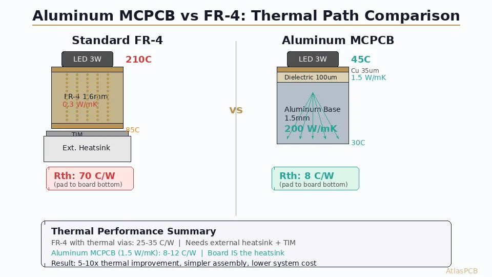
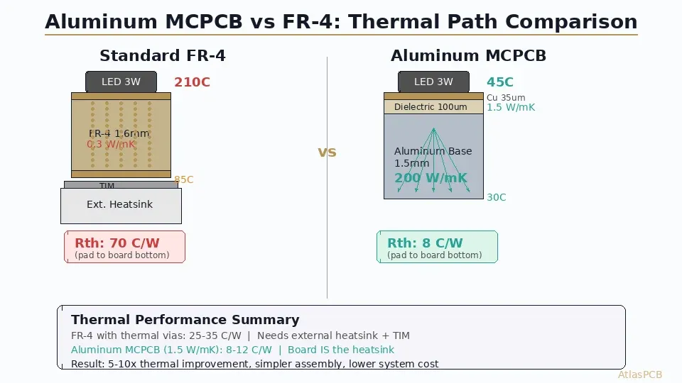
The fundamental limitation of FR-4 as a thermal substrate is not controversial—it is simply physics. With through-thickness thermal conductivity of 0.3 W/mK, a standard 1.6mm FR-4 board presents a thermal resistance of approximately 70 C/W per square centimeter. A 3W LED package on FR-4 without thermal relief will see a 210C temperature rise from board bottom to junction, which is obviously catastrophic.
Engineers have developed workarounds—thermal vias, copper pours, exposed copper pads with thermal interface material to external heatsinks—but these add complexity, assembly steps, and cost. The thermal via approach works reasonably well for moderate power (arrays of 0.3mm vias on 0.6mm pitch can reduce effective thermal resistance by 60-70%), but the copper fill ratio is limited by drill density rules, and the heat still needs somewhere to go once it reaches the bottom copper layer.
The real question is not whether aluminum MCPCB is thermally superior—it always is—but whether your specific design’s thermal requirements justify the constraints that metal-core construction imposes on routing, layer count, and component placement.
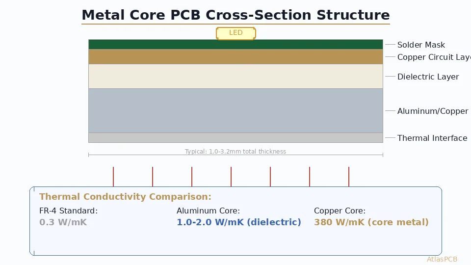
Aluminum MCPCB Construction and Thermal Path
An aluminum MCPCB consists of three functional layers: the circuit copper layer (35-140um), a thermally conductive dielectric layer (75-200um), and the aluminum base plate (0.8-3.2mm). The dielectric is the critical engineering layer—it must simultaneously provide electrical isolation (typically rated at 3-6 kV breakdown) and thermal conduction. Modern MCPCB dielectrics achieve this through ceramic fillers (alumina or boron nitride particles) dispersed in an epoxy or polyimide matrix.
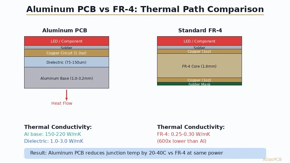
The thermal path is elegantly simple compared to FR-4: heat flows from the component pad through 35-70um of copper, then through 75-200um of filled dielectric (1.0-3.0 W/mK), and immediately enters the aluminum base plate (200 W/mK) which acts as a built-in heatspreader. The total thermal resistance from pad to base plate bottom is typically 5-15 C/W per square centimeter—roughly a 5-10x improvement over FR-4.
This direct thermal path eliminates the need for thermal vias, thermal interface materials between board and heatsink (the board IS the heatsink), and often the heatsink itself for moderate power applications. A well-designed aluminum MCPCB can dissipate 3-5W per LED without any additional thermal management beyond convective airflow over the exposed aluminum back surface.
THERMAL DESIGN SUPPORT
Need Help Choosing Between MCPCB and FR-4?
Our engineers review thermal requirements and recommend the optimal substrate for your power density and cost targets.
Get Substrate Recommendation ›Thermal Performance Data: Real Numbers
Understanding the thermal performance gap requires looking at actual measured values rather than theoretical comparisons. The following data represents production boards measured using JEDEC JESD51-compliant thermal test methods.
| Parameter | FR-4 (1.6mm) | FR-4 + Thermal Vias | Aluminum MCPCB (1.6mm, 1.5 W/mK) | Aluminum MCPCB (1.6mm, 3.0 W/mK) |
|---|---|---|---|---|
| Board thermal conductivity (through-thickness) | 0.3 W/mK | 0.8-1.2 W/mK (effective) | 1.5 W/mK (dielectric) | 3.0 W/mK (dielectric) |
| Thermal resistance (pad to board bottom, per cm2) | 70 C/W | 25-35 C/W | 12-15 C/W | 6-8 C/W |
| Junction rise at 3W dissipation | 210C (failure) | 75-105C | 36-45C | 18-24C |
| Maximum practical power density | 0.5 W/cm2 | 1.5 W/cm2 | 4 W/cm2 | 8 W/cm2 |
| Heatsink required? | Yes, always at >1W | Often yes | No, up to 3-5W/device | No, up to 8-10W/device |
These numbers demonstrate that aluminum MCPCB is not merely incrementally better—it is a fundamentally different thermal regime. The elimination of the heatsink attachment step alone saves $0.30-1.00 per unit in assembly cost at volume, which partially offsets the higher board cost.
Design Constraints and Trade-offs
Aluminum MCPCB is not a universal solution, and understanding its limitations is as important as knowing its thermal advantages. The single most significant constraint is layer count: the vast majority of aluminum MCPCB production is single-layer (one copper circuit layer on one dielectric layer on one aluminum base). This means your entire circuit must route on a single layer, which limits complexity to approximately 50-80 components for typical LED or power supply designs.
Double-sided aluminum MCPCB exists but requires thermal vias through the aluminum core (which must be electrically isolated) and dramatically increases cost—typically 4-6x over single-sided MCPCB. At that price point, a conventional multilayer FR-4 with embedded copper coins or heavy copper thermal planes often provides better value.
The routing density on single-sided MCPCB is further limited by typical design rules: minimum trace/space of 4/4mil (100/100um) is standard, with 6/6mil being more common in production. This is adequate for power and LED circuits where trace count is low and trace widths are driven by current capacity rather than density. But if your design needs a microcontroller with 48+ I/O pins, you likely need FR-4 multilayer regardless of thermal requirements.
Mechanical considerations also differ: aluminum MCPCB machines cleanly with standard carbide routing and scoring tools, but the aluminum base makes depanelization forces higher. V-scoring is preferred over tab routing for rectangular boards. Non-rectangular outlines and internal cutouts are possible but add 20-30% to routing costs compared to equivalent FR-4 boards.
METAL CORE PCB FABRICATION
Aluminum and Copper MCPCB Production
Single-sided, double-sided, and hybrid constructions. 1.0-3.0 W/mK dielectric options with aluminum or copper base.
View Capabilities ›Application Decision Matrix
The choice between aluminum MCPCB and FR-4 is ultimately application-driven. Each major application category has a clear preference based on decades of industry practice and reliability data.
LED Lighting (commercial, automotive, architectural): Aluminum MCPCB is the default choice. Individual LED packages dissipate 1-5W and require junction temperatures below 85-120C for rated lifetime. A 10-LED linear array on aluminum MCPCB with natural convection easily maintains junction temperatures 40-60C below the same design on FR-4 with thermal vias. The routing simplicity of LED circuits (series-parallel strings with minimal control logic) fits single-layer MCPCB perfectly.
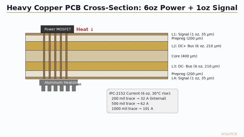
Motor Drivers and Half-Bridge Circuits: MCPCB excels here because MOSFET packages (D2PAK, TO-263) dissipate 5-20W switching losses concentrated in a small area. The aluminum base spreads this localized heat across a larger area for more effective convection or conduction to a chassis. However, gate driver and control circuits often require a separate FR-4 daughter board or a hybrid construction.
Power Supplies (AC-DC, DC-DC converters above 50W): Mixed results. The power stage benefits from MCPCB thermal performance, but control loops, feedback networks, and EMI filtering require routing density that single-layer MCPCB cannot provide. Hybrid approaches—MCPCB power board connected to FR-4 control board—are common in industrial power supplies above 100W.
Automotive Electronics: Increasingly aluminum MCPCB for headlamps, DRLs, and exterior lighting. The thermal and vibration performance of aluminum base boards exceeds FR-4 in automotive temperature ranges (-40C to +125C ambient). AEC-Q certification of MCPCB materials is now standard from major suppliers.
LED AND POWER PCB EXPERTISE
From Prototype to Production Volume
Upload your Gerber files for instant pricing on aluminum MCPCB, copper MCPCB, or FR-4 with thermal via optimization.
Upload Gerber Files ›Cost Analysis: Board Cost vs System Cost
The raw board cost comparison between aluminum MCPCB and FR-4 is misleading without system-level context. A single-layer aluminum MCPCB typically costs 2-4x more per unit area than equivalent single-layer FR-4. For a 50x50mm single-layer board at 100-piece quantity, expect $2.50-4.00 per board for aluminum MCPCB versus $0.80-1.50 for FR-4.
However, system-level cost analysis often reverses this calculation. A high-power LED design on FR-4 requires: thermal vias (add $0.20-0.40/board for drilling), an external aluminum heatsink ($1.00-5.00), thermal interface material ($0.15-0.50), mounting hardware ($0.10-0.30), and additional assembly labor for heatsink attachment ($0.30-1.00). The total thermal system cost on FR-4 often exceeds $2.00-7.00 per unit—more than the MCPCB premium.
For prototyping quantities (5-25 pieces), MCPCB’s higher NRE cost and limited sourcing options favor FR-4 for initial validation. Switch to MCPCB for production when thermal testing confirms the need and volumes justify the tooling.
Specification Guidelines for Your Fab Drawing
When specifying aluminum MCPCB on your fabrication drawing, include these critical parameters that differ from standard FR-4 callouts:
The base material specification must include aluminum alloy grade (5052 or 6061 are standard for MCPCB), base thickness (1.0, 1.5, or 2.0mm typical), and surface finish of the aluminum back (bare, anodized, or pre-applied thermal interface). The dielectric must specify thermal conductivity class (1.0, 1.5, 2.0, or 3.0 W/mK), thickness tolerance (typically plus/minus 25um), and breakdown voltage requirement. Copper weight on the circuit layer follows standard conventions (1oz, 2oz) but note that heavy copper (3oz+) on MCPCB requires different etching parameters than FR-4 and should be confirmed with your fabricator.
Board flatness is more critical for MCPCB than FR-4 because the rigid aluminum base does not conform to mounting surfaces. Specify bow and twist limits of 0.5% or tighter for boards that mount directly to chassis surfaces. AtlasPCB produces metal-core PCBs with aluminum and copper bases in thicknesses from 1.0 to 3.2mm, with dielectric thermal conductivities from 1.0 to 3.0 W/mK.
ATLASPCB
Ready to Optimize Your Thermal Design?
Get pricing for aluminum MCPCB, copper MCPCB, or FR-4 with thermal via arrays. Upload your design files for a detailed quotation.
Get Instant Quote ›Related Reading:
About AtlasPCB — We specialize in complex PCB manufacturing for HDI, RF, and high-reliability applications. Explore our heavy copper PCB manufacturing, or get an aluminum PCB manufacturing . Every order includes free engineering review. Get your quote.
Reviewed by AtlasPCB Engineering Team — IPC-certified manufacturing specialists with 15+ years of production experience in HDI, RF, and high-reliability PCB fabrication. Content based on factory floor data and real customer design reviews.
- aluminum PCB
- metal core PCB
- MCPCB
- FR-4
- thermal management
- LED PCB
- power electronics