· AtlasPCB Engineering · Engineering · 10 min read
PCB Power Integrity Design: Decoupling Capacitor Placement, PDN Impedance, and Voltage Droop Prevention
Complete guide to PCB power delivery network (PDN) design covering decoupling capacitor selection and placement, target impedance calculation, power plane cavity resonance, and practical voltage droop prevention strategies for high-speed digital systems operating at 1V and below.
Why Power Integrity Is the Hidden Performance Limiter
Every signal integrity problem has a power integrity root cause waiting to be discovered. When your 10 Gbps SerDes link shows unexplained jitter, when your ADC’s ENOB drops by two bits under load, when your processor throws intermittent errors during burst computation — the culprit is often a poorly designed Power Delivery Network (PDN).
Power integrity (PI) has become the defining challenge of modern PCB design because:
- Core voltages keep dropping — Modern processors run at 0.7-1.0V, leaving almost no noise margin
- Transient currents keep rising — A modern FPGA can demand 50A+ step-load changes in nanoseconds
- Switching frequencies keep increasing — GHz clock rates mean femtosecond-scale timing margins
This guide provides a systematic approach to PDN design that works across complexity levels — from simple microcontroller boards to multi-gigahertz server systems.
The PDN Impedance Model
A PCB’s power delivery network is best understood as a frequency-dependent impedance seen from the IC’s power pins looking back toward the voltage regulator. At every frequency, this impedance must stay below the target value:
Ztarget = Vdd × Ripple_Tolerance / I_transient_maxExample Calculation
For a processor core rail:
- Vdd = 0.9V
- Allowable ripple = ±3% (±27mV)
- Maximum transient current = 30A
Ztarget = 0.9 × 0.03 / 30 = 0.9 mΩ
This means the PDN impedance — as seen from the IC — must remain below 0.9 milliohms from DC all the way up to the processor’s maximum switching frequency. That’s an extraordinarily low impedance target, and it requires careful coordination of multiple PDN elements.
Frequency Domains of the PDN
Each element in the PDN “owns” a specific frequency band:
| PDN Element | Effective Range | Typical Impedance |
|---|---|---|
| VRM (regulator) | DC – 10 kHz | Set by regulation loop |
| Bulk electrolytic caps | 1 kHz – 100 kHz | 10-100 mΩ |
| Bulk MLCC (47-100 μF) | 10 kHz – 2 MHz | 2-20 mΩ |
| Decoupling MLCC (100nF-1μF) | 500 kHz – 100 MHz | 1-10 mΩ |
| High-freq MLCC (1-10 nF) | 10 MHz – 500 MHz | 1-5 mΩ |
| Power/ground plane pair | 100 MHz – 2 GHz | 0.5-5 mΩ |
| On-die capacitance | >1 GHz | IC-dependent |
The art of PDN design is ensuring smooth impedance handoff between these elements with no resonant peaks (anti-resonances) that exceed the target.
Decoupling Capacitor Selection
Understanding Capacitor Behavior at Frequency
A real capacitor is not just capacitance — it’s an RLC circuit:
- ESR (Equivalent Series Resistance): Dominates at the self-resonant frequency (SRF)
- ESL (Equivalent Series Inductance): Dominates above SRF — capacitor becomes an inductor
- Capacitance: Dominates below SRF — provides decreasing impedance with frequency
The self-resonant frequency (SRF) where impedance is minimum:
SRF = 1 / (2π × √(L × C))For a typical 100nF 0402 MLCC with 0.5nH ESL: SRF = 1 / (2π × √(0.5×10⁻⁹ × 100×10⁻⁹)) = 22.5 MHz
Above 22.5 MHz, this capacitor behaves as an inductor, not a capacitor.
Capacitor Value Selection Strategy
Select capacitor values to create overlapping coverage across the frequency spectrum:
| Capacitor Value | Package | SRF (typical) | Effective Band |
|---|---|---|---|
| 100 μF | 1210 | ~500 kHz | 100 kHz – 2 MHz |
| 10 μF | 0805 | ~2 MHz | 500 kHz – 5 MHz |
| 1 μF | 0402 | ~7 MHz | 2 – 20 MHz |
| 100 nF | 0402 | ~22 MHz | 5 – 50 MHz |
| 10 nF | 0201 | ~70 MHz | 20 – 150 MHz |
| 1 nF | 0201 | ~220 MHz | 50 – 500 MHz |
Anti-Resonance: The Hidden Killer
When two capacitors of different values are connected in parallel, they form an LC circuit at the frequency where the larger cap becomes inductive and the smaller cap is still capacitive. This creates an anti-resonance peak — a frequency where PDN impedance spikes dramatically.
Mitigation strategies:
- Use many different values — More values = smaller anti-resonance peaks
- Add lossy capacitors — Higher ESR damps resonances (some designers intentionally add resistance)
- Rely on plane capacitance — At high frequencies, the power/ground plane pair provides broadband capacitance with inherent damping
- Simulate, don’t guess — PDN simulation tools (Ansys SIwave, Cadence Sigrity PowerSI) reveal anti-resonance locations
Capacitor Placement: The Physics
Below 50 MHz: Placement Doesn’t Matter Much
At frequencies below ~50 MHz, the wavelength in FR-4 (λ = c / (f × √εr) ≈ 150mm / f_GHz) exceeds the board dimension. The entire power plane acts as a single equipotential node, so capacitor location has minimal impact.
Practical implication: Bulk capacitors (10μF, 100μF) can be placed anywhere convenient on the board — near the VRM, along board edges, or wherever space permits.
Above 50 MHz: Every Millimeter Counts
Above 50 MHz, connection inductance between the capacitor and the IC dominates. The inductance of a via + short trace is approximately:
- Single via: ~0.5-1.0 nH
- Trace (per mm): ~0.7-1.0 nH/mm
- Via pair (signal + return): ~0.3-0.7 nH
At 200 MHz, 1 nH of inductance presents: Z = 2π × 200×10⁶ × 1×10⁻⁹ = 1.26 Ω
That’s 1,000× higher than a typical target impedance! This is why high-frequency decoupling must be placed within 2mm of IC power pins.
Optimal Placement Rules
- Place 1-10 nF caps within 1-2mm of IC power/ground pin pairs — Use shortest possible via connections
- Place 100nF caps within 5mm of IC — Still effective up to ~50 MHz
- Place 1-10μF caps within 10-15mm — Effective up to ~10 MHz
- Place bulk caps (47-100μF) anywhere on the board — Their effective range is below where placement matters
Via Connection Optimization
The connection between a decoupling capacitor and the power/ground planes is critical:
Best practice:
- Use multiple vias per cap pad (2 vias per pad for 0402, 3-4 for 0805+)
- Connect vias directly to pad — no trace between pad and via
- Use via-in-pad when possible (requires resin fill to prevent solder wicking)
- Route the power via and ground via as close together as possible to minimize loop inductance
Complex Multi-Layer Stackup with Tight PDN Requirements?
AtlasPCB specializes in 12-40 layer PCBs with controlled impedance and optimized power plane pairs. Our DFM team reviews PDN via structures and ensures manufacturing supports your power integrity goals.
Get Engineering Review →Power Plane Design
Plane Pair Capacitance
A parallel-plate capacitor is formed by every adjacent power/ground plane pair:
C_plane = ε₀ × εr × Area / thicknessFor a typical configuration:
- Area: 100mm × 80mm = 8,000 mm²
- Dielectric thickness: 0.1mm (4 mil)
- εr: 4.2 (FR-4)
C_plane = 8.854×10⁻¹² × 4.2 × 8×10⁻³ / 0.1×10⁻³ = 3.0 nF
This 3nF of plane capacitance is distributed across the entire board area with very low inductance — it’s the most effective high-frequency PDN element.
Designing for Plane Capacitance
To maximize plane-pair capacitance:
- Minimize dielectric spacing — Use thin prepreg (2-4 mil) between power/ground pairs
- Maximize plane area — Avoid splits and cutouts in the power region under ICs
- Use higher-εr materials — Some manufacturers offer εr=7-10 capacitive laminates
- Place power/ground pairs adjacent — Never separate them with signal layers
Stackup Recommendations for Power Integrity
A well-designed multilayer stackup considers PDN requirements from the start:
12-layer example (optimized for PDN):
Layer 1:  Signal (Top)
Layer 2:  GND ←→ tight coupling to L1 (reference)
Layer 3:  Signal
Layer 4:  POWER ←→ thin core to L5 (PDN capacitance)
Layer 5:  GND
Layer 6:  Signal
Layer 7:  Signal
Layer 8:  GND ←→ thin core to L9 (PDN capacitance)
Layer 9:  POWER
Layer 10: Signal
Layer 11: GND ←→ tight coupling to L12 (reference)
Layer 12: Signal (Bottom)
Key features:
- Power/ground pairs (L4-L5, L8-L9) use thin dielectric (3-4 mil) for maximum capacitance
- Every signal layer has an adjacent ground reference for controlled impedance
- Two PDN capacitor pairs provide broadband high-frequency decoupling
Voltage Droop Analysis
What Causes Voltage Droop
When an IC transitions from idle to active state, it demands a step increase in current. The PDN must supply this current without the voltage dropping below the IC’s minimum operating voltage. The voltage drop depends on:
- Resistive droop (V = I × R): From DC resistance of planes, vias, and traces
- Inductive droop (V = L × di/dt): From connection inductance during fast transients
- Resonance-induced overshoot: From PDN resonances excited by the current step
First Droop and Second Droop
Power integrity engineers distinguish between two droop events:
- First droop (10-50 ns): Limited by on-die capacitance and nearest decoupling caps. The IC’s internal capacitance absorbs the initial transient.
- Second droop (100 ns - 10 μs): Limited by board-level decoupling and VRM response. This is typically the deeper droop event that determines minimum operating voltage.
Droop Budget Example
For a 1.0V core rail with ±5% tolerance (50mV budget):
| Source | Allocation | Controlled By |
|---|---|---|
| VRM static accuracy | ±10mV | VRM selection |
| Resistive droop (DC) | 10mV | Plane resistance, via count |
| First droop (fast transient) | 10mV | On-die caps, immediate decoupling |
| Second droop (VRM response) | 15mV | Bulk caps, VRM bandwidth |
| Margin | 5mV | Design safety |
Practical Design Guidelines
Rule-of-Thumb PDN Checklist
For a typical high-speed digital board:
- Target impedance calculated for each power rail
- Stackup includes at least one thin-core power/ground pair
- 1nF-10nF caps within 2mm of every high-speed IC power pin
- 100nF caps within 5mm of every IC (one per power pin minimum)
- 10-100μF bulk caps near VRM output (1 per 5A of load current)
- No power plane splits under ICs
- Via-in-pad or adjacent via for all decoupling caps
- Power plane pour connected with multiple vias at each junction
- Ferrite beads avoided on high-current paths (use controlled impedance instead)
- PDN simulation performed at critical frequencies
Common Mistakes
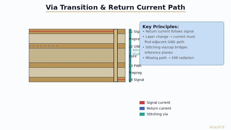
- Insufficient via connections — A single via on each cap pad adds ~1nH, negating the capacitor’s effectiveness above 50MHz
- Plane splits under ICs — Creates return current discontinuities and eliminates plane capacitance exactly where it’s needed
- Excessive trace between cap and via — Even 2mm of trace adds significant inductance at high frequencies
- Wrong capacitor values — Using only 100nF (the “classic” bypass cap) leaves gaps below 5MHz and above 50MHz
- Ignoring ESL specifications — Two 100nF caps with different ESL provide different effective frequency ranges
Simulation-Driven Design Flow
Modern PDN design should follow this flow:
- Define requirements — Target impedance from IC datasheet and current profile
- Design stackup — Allocate plane pairs for each power domain
- Place ICs and decoupling — Follow placement rules above
- Simulate PDN impedance — Verify target impedance is met DC to max frequency
- Identify anti-resonances — Add capacitor values or damping to eliminate peaks
- Verify with transient simulation — Confirm voltage stays within spec under worst-case load step
- Validate in hardware — Measure with VNA or TDR after prototyping
Advanced Topics
Embedded Capacitance Technology
For the most demanding applications (>10 GHz processors, AI accelerators), discrete capacitors may be insufficient. Embedded capacitance solutions include:
- Thin-film embedded capacitors: Ceramic layers within the PCB stackup providing 10-50 nF/cm²
- Capacitive laminates: High-εr materials (εr=10-20) in dedicated plane-pair layers
- Embedded components: Physical capacitors buried inside the PCB substrate
These technologies add cost but provide unmatched high-frequency PDN performance with zero connection inductance.
Multi-Rail PDN Interaction
Modern ICs have multiple power rails (core, I/O, PLL, analog) that share the same ground return. Coupling between rails through shared ground impedance can cause:
- PLL jitter from digital core switching noise
- ADC performance degradation from digital crosstalk via PDN
- I/O signal quality issues from core transients
Mitigation: Separate the ground return paths physically (dedicated ground layers per domain) or frequency-isolate with ferrite beads on the less-critical rail.
Conclusion and Design Resources
Power integrity is no longer optional — it’s the foundation upon which signal integrity, timing margins, and system reliability are built. A well-designed PDN:
- Reduces EMI at the source (less voltage ripple = less radiated noise)
- Improves signal integrity (cleaner power = cleaner signals)
- Extends component life (less thermal stress from ripple currents in capacitors)
- Enables higher clock frequencies (more noise margin for timing)
For boards with critical power integrity requirements, AtlasPCB provides:
- Stackup design consultation — Optimized plane pairs for your specific PDN requirements
- Controlled impedance verification — TDR-verified impedance including power plane characterization
- Via-in-pad capability — Resin-filled and plated-over for optimal decoupling placement
- Thin core processing — Down to 2 mil (50μm) core for maximum plane capacitance
Request a stackup review → — Our engineering team will analyze your PDN requirements and recommend an optimal layer assignment.
Further reading: [Multilayer PCB Stackup Design Guide]/blog/multilayer-pcb-stackup-design-guide/) | [Controlled Impedance PCB Design]/blog/controlled-impedance-pcb-stackup-design-rules/) | [PCB EMI Compliance]/blog/pcb-design-emi-compliance/) | [HDI PCB Design Guide]/blog/hdi-pcb-design-guide/)
About AtlasPCB — We specialize in complex PCB manufacturing for HDI, RF, and high-reliability applications. Explore our impedance-controlled PCB manufacturing . Every order includes free engineering review. Get your quote.
Reviewed by AtlasPCB Engineering Team — IPC-certified manufacturing specialists with 15+ years of production experience in HDI, RF, and high-reliability PCB fabrication. Content based on factory floor data and real customer design reviews.
- power integrity
- PDN
- decoupling capacitors
- PCB design
- target impedance
- voltage droop
- power planes
- signal integrity
- high-speed digital
- EMI