· AtlasPCB Engineering · Engineering · 7 min read
MEMS Active Cooling for Edge AI: How Piezoelectric µCooling Changes PCB Thermal Design
xMEMS and other MEMS cooling startups are bringing sub-1mm active cooling to edge AI devices. Learn how piezoelectric micro-coolers work, their impact on PCB thermal design, and what hardware engineers need to consider for AI glasses, SSDs, and compact NPU boards.

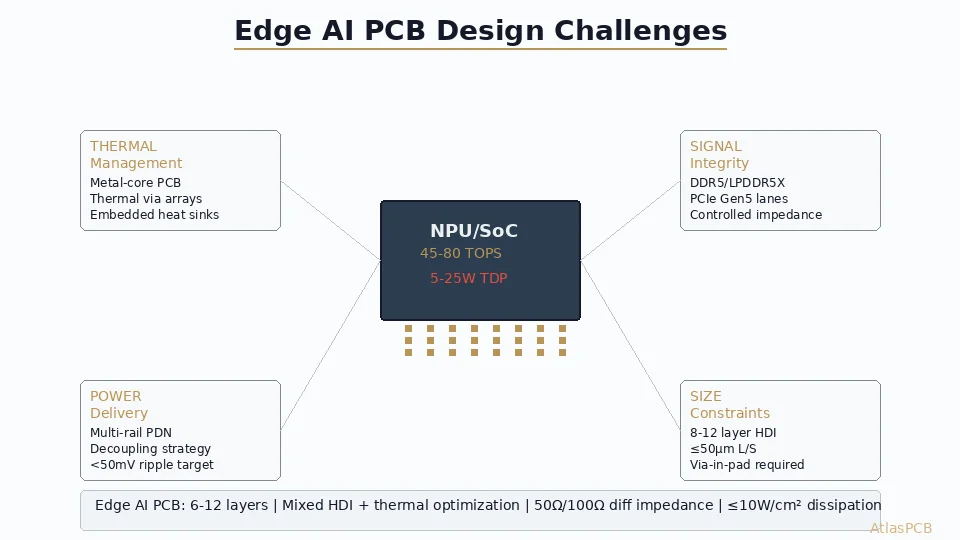
The Edge AI Thermal Challenge
Edge AI processors are getting more powerful while their form factors shrink. AR/VR headsets, AI cameras, smart glasses, and NVMe SSDs with on-device inference all face the same constraint: thermal dissipation in millimeter-scale Z-height budgets.
Traditional cooling solutions don’t fit:
- Fans: Minimum 5mm height, audible noise, reliability concerns (bearings)
- Heat pipes: 2–4mm minimum, require distant heat spreader area
- Passive heatsinks: Insufficient for sustained AI workloads > 5W in sealed enclosures
MEMS-based micro-cooling is emerging as the solution. xMEMS Labs announced (June 2026, DIGITIMES/Computex) that its piezoelectric µCooling technology targets commercial production in 2027, with AI glasses and data center SSDs as primary applications. This isn’t a distant future technology—hardware engineers need to understand PCB implications now.

How MEMS Piezoelectric Cooling Works
Operating Principle
A MEMS micro-cooler consists of an array of thin piezoelectric membranes (PZT, AlN, or PVDF) fabricated on a silicon substrate:
- Actuation: Applying an AC voltage at the membrane’s resonant frequency (100–200 kHz) causes it to flex rapidly—creating alternating positive and negative pressure
- Jet formation: During the downstroke, air is drawn in from the sides. During the upstroke, air is expelled as a concentrated micro-jet directed at the hot surface below
- Entrainment: Each micro-jet entrains surrounding air, multiplying the effective airflow volume by 3–5×
- Heat transfer: Forced convection from the jet array removes heat from the surface, with heat transfer coefficients reaching 500–1000 W/m²·K (vs. 5–25 W/m²·K for natural convection)
Performance Specifications (2026–2027 Generation)
| Parameter | Typical Value |
|---|---|
| Actuator array size | 10×10mm to 30×30mm |
| Total thickness | 0.5–1.0 mm |
| Operating frequency | 100–200 kHz |
| Audible noise | < 20 dBA (inaudible) |
| Power consumption | 50–200 mW |
| Cooling capacity | 5–15 W (device-dependent) |
| Thermal resistance | 3–8 °C/W (system level) |
| Lifetime | > 100,000 hours (no bearings) |
| Operating voltage | 3.3–5V drive |
Advantages Over Traditional Cooling
vs. Micro-fans (blowers):
- 5× thinner (1mm vs 5mm)
- No bearings (> 10× reliability improvement)
- No audible noise at any speed
- No vibration coupling to optical sensors
vs. Passive heatsinks:
- 3–5× better thermal performance in same volume
- Maintains cooling during sustained AI inference
- Can be dynamically controlled based on workload
vs. Vapor chambers:
- No orientation sensitivity
- Faster thermal response (microseconds vs milliseconds)
- Better for intermittent high-power bursts (AI inference spikes)
PCB Thermal Design for MEMS Cooling
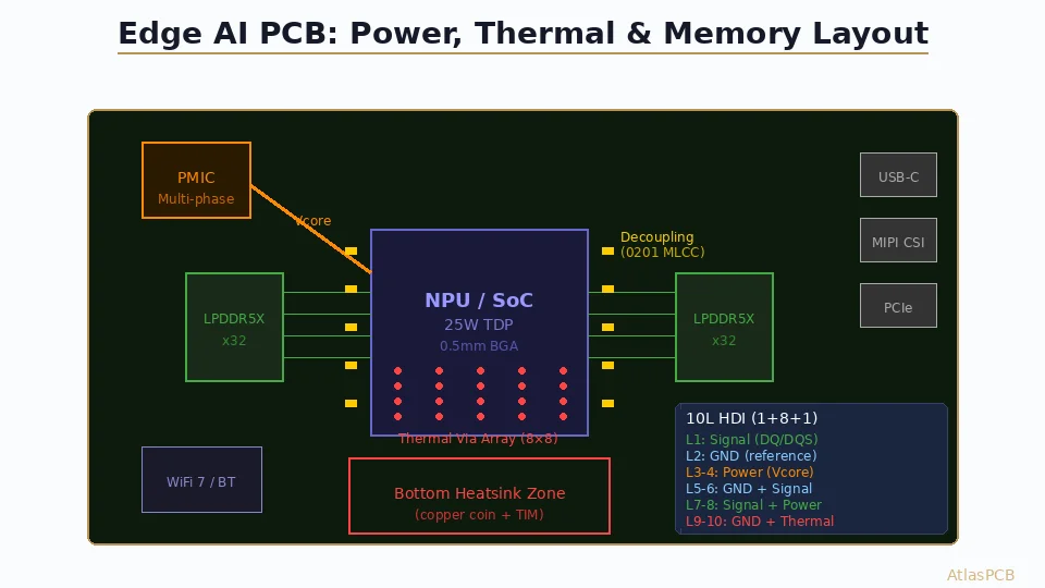
Thermal Via Array Requirements
The PCB directly beneath the AI chip must efficiently conduct heat from the die through the board to the MEMS cooler mounting surface:
Via array design:
- Via diameter: 0.3mm (12 mil) filled and plated over
- Via pitch: 0.8–1.0mm (maximum density in thermal pad area)
- Fill material: Copper-filled preferred (3–5× better than epoxy-plugged)
- Target thermal conductivity: 20–40 W/m·K effective (vs 0.3 W/m·K for bare FR-4)
Thermal resistance stack:
Die junction → TIM1 → Package lid/heat spreader → TIM2 → MEMS cooler → Air
     or
Die junction → TIM → Exposed pad → Thermal vias → Bottom copper pad → TIM → MEMS cooler → Air
For direct die-attach (no lid) designs common in edge AI:
- Total Rth target: < 10°C/W (junction to ambient)
- PCB contribution: < 3°C/W (requires copper-filled vias)
- MEMS cooler contribution: 3–8°C/W
Keepout Zone Design
MEMS actuators vibrate at ultrasonic frequencies. While inaudible, the acoustic energy can:
- Create sympathetic vibration in nearby SMT components (especially ceramic capacitors)
- Generate acoustic noise if coupled to mechanical resonances of the enclosure
- Interfere with MEMS sensors (accelerometers, gyroscopes, microphones) on the same PCB
Design rules:
- Mechanical keepout: No tall components within 2mm of MEMS cooler perimeter
- MEMS sensor separation: > 10mm from any MEMS microphone or IMU
- Capacitor orientation: Orient MLCC capacitors perpendicular to the cooler membrane plane (reduces acoustic coupling)
- Board stiffness: Minimum 1.6mm board thickness in the MEMS cooler zone to prevent PCB flexing at drive frequency
Power Delivery for MEMS Driver
The MEMS cooler requires a driver IC that generates the high-frequency AC drive signal:
- Typical power: 50–200 mA at 3.3–5V
- Waveform: Sinusoidal or shaped pulse at resonant frequency
- Control interface: I²C or SPI for speed/mode control
PCB routing considerations:
- Dedicated LDO or power rail for MEMS driver (avoid sharing with sensitive analog)
- Ferrite bead isolation from main digital power to prevent EMI
- Decoupling: 4.7µF + 100nF close to driver IC
- Trace width: ≥ 15 mil for 200 mA capacity
Building Edge AI Hardware with MEMS Cooling?
AtlasPCB provides copper-filled via arrays, precise thermal pad manufacturing, and thin-board technology for MEMS-cooled AI applications.
Discuss Your Thermal Design →Application-Specific PCB Considerations
AI Glasses and AR Headsets
Constraints: Total board thickness < 0.8mm, weight budget < 2g for cooling, no audible noise, proximity to optical sensors.
PCB approach:
- 4-layer rigid-flex with embedded copper coins under NPU
- MEMS cooler on the temple arm exterior surface
- Thermal bridge: flexible copper strap from NPU to cooler
- Total Z-height budget: 0.8mm PCB + 0.5mm cooler = 1.3mm
NVMe SSDs with AI Inference
Constraints: M.2 2280 form factor (22×80×2.3mm), 5–8W during inference, no airflow in laptop enclosure.
PCB approach:
- MEMS cooler replaces traditional SSD heatsink sticker
- Thermal vias beneath NAND and controller
- Cooler draws air along the length of the SSD and exhausts at the card edge
- Power from 3.3V SSD supply rail (budget: 150mW for cooler)
Embedded Vision and AI Cameras
Constraints: Sealed IP67 enclosure, 10–25W sustained inference, ambient to 85°C.
PCB approach:
- MEMS cooler array (multiple units) inside sealed cavity
- Internal circulation: cooler moves air over internal heatsink
- Heat conducted to metal housing via thermal pad
- No external airflow required—internal forced convection sufficient
Thermal Simulation Considerations
CFD Modeling of MEMS Airflow
Traditional CFD tools (ANSYS Icepak, FloTHERM) need adaptation for MEMS jet arrays:
- Model individual jets as velocity boundary conditions (not spinning fan geometry)
- Include entrainment effects (jet-jet interaction)
- Account for confined space between cooler and heat source (gap typically 0.3–0.5mm)
- Validate against manufacturer’s published performance maps
Thermal Transient Behavior
MEMS coolers excel at handling thermal transients—the bursty nature of AI inference:
- Response time: < 10ms to full cooling capacity (vs 2–5 seconds for fan spinup)
- AI workloads typically: 500ms inference burst, then idle
- Dynamic power scaling: reduce MEMS drive amplitude during idle (saves 80% of cooler power)
This matches edge AI usage patterns far better than thermal mass-based solutions.
Manufacturing and Assembly Considerations
MEMS Cooler Attachment
- TIM selection: Phase-change material or graphite pad (thermal grease too thin for MEMS gap maintenance)
- Flatness requirement: Mounting surface flatness < 25 µm (standard FR-4 may need copper coin for compliance)
- Adhesive vs mechanical: MEMS modules typically use pressure-sensitive adhesive with defined bond-line thickness
Rework Considerations
- MEMS cooler can be removed and replaced without board damage
- TIM replacement required after removal
- No solder interconnect (mechanical/adhesive mount only)
- Board-side thermal vias unaffected by cooler replacement
The Roadmap: 2026–2028
| Timeline | Milestone |
|---|---|
| H2 2026 | Engineering samples from xMEMS, Frore Systems |
| 2027 | Commercial production, first AI glasses with MEMS cooling |
| 2027–2028 | Data center SSD integration, automotive ADAS adoption |
| 2028+ | Multi-chip module (MCM) integration, co-packaged cooling |
For PCB designers working on next-generation edge AI products with 2027–2028 launch targets, now is the time to understand MEMS cooling constraints and design stackups accordingly.
Design Checklist for MEMS-Cooled PCBs
- ☐ Define thermal via array density (target ≤ 5°C/W through board)
- ☐ Specify copper-filled vias in thermal zone
- ☐ Design MEMS mounting pad with ≤ 25 µm flatness spec
- ☐ Establish 2mm mechanical keepout around cooler perimeter
- ☐ Separate MEMS driver power from sensitive analog rails
- ☐ Verify no MEMS sensors within 10mm of cooler
- ☐ Include airflow channels in enclosure design (inlet/outlet)
- ☐ Specify board stiffness in cooler zone (≥ 1.6mm thickness)
- ☐ Plan for dynamic power management (I²C/SPI control interface)
- ☐ Validate thermal performance with CFD simulation including jet model
Further Reading
- Thermal Via Design for PCB Heat Dissipation
- PCB Copper Coin Thermal Management
- Flex and Rigid-Flex PCB Design Guidelines
- High-Tg PCB Material Selection
Developing edge AI hardware with aggressive thermal constraints? AtlasPCB manufactures PCBs with copper-filled thermal via arrays, embedded copper coins, and the precision required for MEMS cooling integration. Get a quote for your next-generation edge AI design.
About AtlasPCB — We specialize in complex PCB manufacturing for HDI, RF, and high-reliability applications. Explore our aluminum and metal-core PCB services . Every order includes free engineering review. Get your quote.
Reviewed by AtlasPCB Engineering Team — IPC-certified manufacturing specialists with 15+ years of production experience in HDI, RF, and high-reliability PCB fabrication. Content based on factory floor data and real customer design reviews.
- MEMS cooling
- edge AI
- thermal design
- PCB layout
- xMEMS
- piezoelectric
- NPU
- thermal management