· AtlasPCB Engineering · Engineering · 9 min read
IPC-A-600 Class 2 vs Class 3: PCB Acceptability Criteria, Defect Classification, and When to Specify Each Class
Understand IPC-A-600 PCB acceptability criteria differences between Class 2 and Class 3. Covers defect classification for annular ring, plating voids, copper thickness, laminate conditions, and marking — with practical guidance on when each class applies to your product.

Introduction: What IPC-A-600 Actually Governs
IPC-A-600 (“Acceptability of Printed Boards”) is the global reference document that defines what constitutes an acceptable bare printed circuit board. It doesn’t tell you how to design or manufacture a PCB — it tells inspectors, manufacturers, and customers whether a finished PCB meets quality requirements.
Published by the IPC (Association Connecting Electronics Industries), IPC-A-600 covers:
- External and internal layer conditions
- Plating quality and thickness
- Hole and via conditions
- Laminate integrity
- Surface conditions
- Marking and identification
- Dimensional tolerances
The standard defines three product classes, each with progressively tighter acceptance criteria. Understanding the practical differences between Class 2 and Class 3 — not just the specification language — is essential for making informed quality/cost trade-offs.
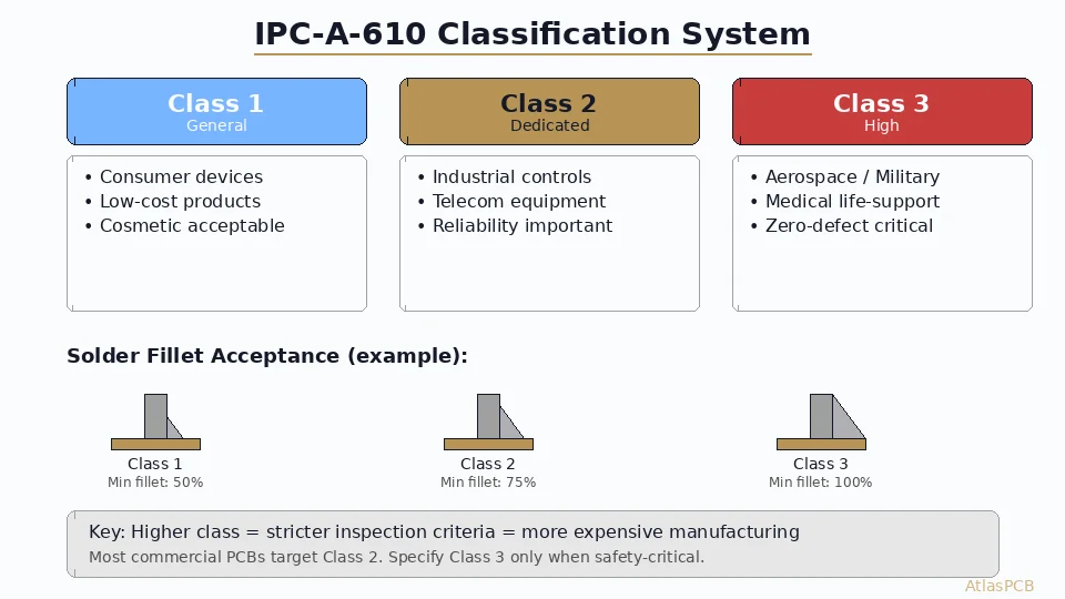
The Three Product Classes
Class 1: General Electronic Products
Products where primary requirement is function of the completed assembly. Includes:
- Disposable consumer electronics
- LED lighting
- Basic IoT sensors
- Non-critical hobby/maker boards
Acceptable quality: Cosmetic defects accepted freely; function is the only criterion.
Class 2: Dedicated Service Electronics
Products where continued performance and extended life is required, but uninterrupted service is not critical. This is the default class for most commercial electronics:
- Smartphones and tablets
- Laptops and desktop computers
- Industrial controls and PLCs
- Networking equipment (commercial grade)
- Automotive non-safety systems (infotainment, comfort)
- Telecommunications (non-carrier-grade)
Acceptable quality: Minor imperfections allowed if they don’t affect expected service life.
Class 3: High-Reliability/Harsh Environment
Products where continued performance or performance-on-demand is critical, where equipment downtime cannot be tolerated, and the end-use environment may be harsh:
- Medical life-support and implantable devices
- Aerospace flight-critical avionics
- Military weapons systems
- Automotive ADAS and powertrain control (ASIL-C/D)
- Nuclear facility control systems
- Satellite and space hardware
- Subsea equipment
Acceptable quality: Near-perfect manufacturing required; any defect that could potentially affect reliability is rejectable.
Critical Differences: Class 2 vs Class 3
1. Annular Ring
The annular ring is the copper remaining between the drill hole edge and the land (pad) edge. It’s one of the most commonly violated criteria.
Class 2:
- External supported holes: 90° breakout acceptable (drill can touch pad edge)
- Internal supported holes: 90° breakout acceptable
- Non-supported holes: 90° breakout acceptable
- Minimum annular ring (when present): 50 µm (2 mil)
Class 3:
- External supported holes: Minimum 50 µm (2 mil) annular ring required
- Internal supported holes: 0° breakout maximum (drill tangent to pad edge, but no actual breakout)
- Non-supported holes: Minimum 50 µm (2 mil) annular ring required
- No breakout permitted on any layer
Practical impact: Class 3 requires larger pads relative to drill sizes. For a 0.3mm (12 mil) drill, Class 3 needs minimum 0.4mm (16 mil) pad diameter, while Class 2 can use 0.35mm (14 mil) or even approach tangency. This directly affects routing density in [HDI designs]/blog/hdi-microvia-stacked-vs-staggered-reliability-en/).
2. Plating Thickness
Copper plating in via barrels:
| Requirement | Class 2 | Class 3 |
|---|---|---|
| Minimum average thickness | 20 µm (0.8 mil) | 25 µm (1.0 mil) |
| Minimum at any point | 18 µm (0.7 mil) | 20 µm (0.8 mil) |
| Plating voids (total area) | ≤5% of barrel surface | 0% (no voids allowed) |
| Individual void max size | ≤5% of barrel length | Not applicable (none allowed) |
Surface copper thickness:
| Requirement | Class 2 | Class 3 |
|---|---|---|
| Minimum (after etching) | Meets design requirement | Meets design requirement |
| Uniformity | ±20% acceptable | ±10% required |
| Surface roughness | No specification | Controlled per material spec |
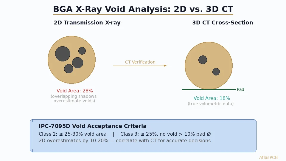
3. Plating Voids
This is arguably the most significant practical difference between the classes.
Class 2: Up to 5% void area in plated through-hole barrels is acceptable. Small voids (micro-voids from gas evolution during plating) are considered cosmetic if they don’t penetrate more than 5% of the barrel length.
Class 3: Zero voids permitted. Any void visible in cross-sectional microsectioning is a reject condition. This single requirement drives:
- Slower plating speeds (more uniform deposition)
- More aggressive desmear/etchback processes
- Higher aspect ratio limitations
- More microsection coupons per panel
- Significantly higher reject rates (5-15% vs <2%)
4. Conductor Width and Spacing
Class 2:
- Conductor width reduction: ≤20% of minimum design value
- Conductor spacing reduction: ≤20% of minimum design value
- Isolated conductor width defects: acceptable if ≤25% of trace length affected
Class 3:
- Conductor width reduction: ≤10% of minimum design value
- Conductor spacing reduction: ≤10% of minimum design value
- Isolated conductor width defects: tighter acceptance criteria
5. Laminate Conditions
Measling and Crazing:
| Condition | Class 2 | Class 3 |
|---|---|---|
| Measling (white spots in laminate) | Acceptable if <1mm from conductor | Not acceptable within conductor area |
| Crazing (connected white fibers) | Acceptable if not bridging conductors | Not acceptable |
| Delamination | <1% of board area, not at edge | Zero tolerance |
| Blistering | <1% per zone, not progressive | Zero tolerance |
Weave texture/exposure:
| Condition | Class 2 | Class 3 |
|---|---|---|
| Glass fiber exposure (surface) | Acceptable if not affecting conductors | Not acceptable |
| Weave texture (surface irregularity) | Acceptable | Acceptable if within flatness spec |
| Haloing (translucent area at holes) | ≤1.5mm from hole edge | ≤0.5mm from hole edge |
6. Surface Conditions
Scratches and dents:
| Condition | Class 2 | Class 3 |
|---|---|---|
| Surface scratches | ≤10% copper thickness depth | ≤5% copper thickness depth |
| Dents/indentations | Not penetrating copper | Not acceptable on conductor areas |
| Pits in plating | ≤5% of pad area | Not acceptable |
| Nodules in plating | ≤5% violation of min spacing | Not acceptable |
Need IPC Class 3 PCBs?
AtlasPCB manufactures to IPC-A-600 Class 2 and Class 3 with full microsection documentation. Our quality system includes 100% AOI and statistical process control.
Get a Class 3 Quote →Inspection Methods
Visual Inspection (Both Classes)
- Magnification: 1.75x-4x for initial inspection, 10x-40x for disposition
- Lighting: Incident light for surface, transmitted light for internal defects
- Equipment: Stereomicroscope or comparable optical inspection system
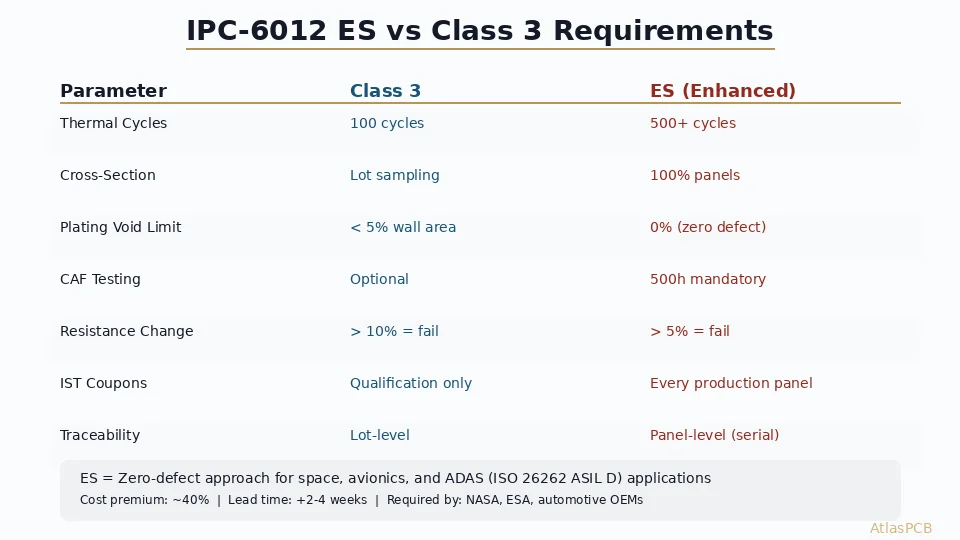
Cross-Sectional Microsectioning (Primarily Class 3)
Microsectioning involves cutting, mounting, polishing, and examining PCB cross-sections under 100x-500x magnification. This destructive test reveals:
- Plating thickness at all points
- Void presence and size
- Annular ring conditions
- Laminate quality
- Inner layer registration
- Etchback/smear removal quality
Class 2: Microsectioning is performed per lot or per statistical sampling plan. Class 3: Microsectioning is performed on coupons from every panel, with specific coupon locations and quantities defined by the procurement specification.
Automated Optical Inspection (AOI)
Both classes benefit from AOI for:
- Conductor width verification
- Spacing verification
- Open/short detection
- Annular ring measurement
However, AOI cannot verify:
- Plating quality in holes (requires cross-section)
- Internal laminate conditions (requires microsection)
- Surface finish thickness (requires XRF)
Design Implications
Pad Sizing for Class 3
To ensure Class 3 annular ring compliance, use these minimum pad sizes:
| Drill Size | Class 2 Min Pad | Class 3 Min Pad | Difference |
|---|---|---|---|
| 0.20 mm (8 mil) | 0.30 mm | 0.40 mm | +0.10 mm |
| 0.25 mm (10 mil) | 0.38 mm | 0.45 mm | +0.07 mm |
| 0.30 mm (12 mil) | 0.43 mm | 0.50 mm | +0.07 mm |
| 0.40 mm (16 mil) | 0.55 mm | 0.60 mm | +0.05 mm |
| 0.50 mm (20 mil) | 0.65 mm | 0.70 mm | +0.05 mm |
Note: Includes drill tolerance, registration tolerance, and minimum annular ring.
Aspect Ratio Considerations
Higher aspect ratios (board thickness ÷ drill diameter) make it harder to achieve uniform plating:
| Aspect Ratio | Class 2 Risk | Class 3 Risk |
|---|---|---|
| ≤6:1 | Low | Low |
| 6:1 - 8:1 | Low | Moderate (void risk increases) |
| 8:1 - 10:1 | Moderate | High (requires pulse plating) |
| >10:1 | High | Very high (specialized process required) |
For Class 3 boards with aspect ratios above 8:1, discuss process capability with your fabricator before finalizing the design. [HDI via structures]/blog/hdi-microvia-stacked-vs-staggered-reliability-en/) with low aspect ratios may be a better approach than deep through-hole vias.
Design Rule Adjustments
When targeting Class 3, adjust your design rules:
| Parameter | Class 2 Design Rule | Class 3 Design Rule |
|---|---|---|
| Min trace width | 3.5 mil (0.09 mm) | 4.0 mil (0.10 mm) |
| Min spacing | 3.5 mil (0.09 mm) | 4.0 mil (0.10 mm) |
| Pad-to-drill ratio | 1.5:1 minimum | 1.7:1 minimum |
| Via-to-pad clearance | 8 mil | 10 mil |
| Board edge clearance | 10 mil | 15 mil |
Cost and Lead Time Impact
Why Class 3 Costs More
| Factor | Impact on Cost |
|---|---|
| Slower plating (void prevention) | +5-10% |
| Additional microsection testing | +3-5% |
| Lower yield (stricter rejection) | +5-15% |
| Premium materials (tighter Dk tolerance) | +5-10% |
| Additional handling care | +2-3% |
| Documentation and traceability | +2-5% |
| Total typical premium | +15-40% |
Lead Time Extension
| Process | Class 2 | Class 3 |
|---|---|---|
| Standard production | 5-7 days | 7-10 days |
| Quick-turn | 3-5 days | 5-7 days |
| Prototype | 24-72 hours | 72-120 hours |
The lead time increase comes primarily from additional testing, inspection, and the higher likelihood of panel rejection requiring re-manufacture.
Mixed-Class Designs
Some products require Class 3 reliability for specific features but don’t need it everywhere. Options include:
Option 1: Full Class 3 (Simplest)
Manufacture entire board to Class 3. Higher cost but simpler specification and inspection.
Option 2: Class 2 Board with Class 3 Features
Specify “IPC-A-600 Class 2 with the following Class 3 requirements: [list specific criteria].” Common selective upgrades:
- Class 3 plating voids requirement only
- Class 3 annular ring on specific critical vias
- Class 3 laminate conditions only
Option 3: Separate Boards
If a mixed-class board is too complex, consider separating critical circuitry onto a Class 3 sub-board connected via connectors to a Class 2 main board.
Common Misconceptions
”Class 3 means better components/materials”
False. IPC-A-600 governs manufacturing quality, not material selection. You can build a Class 3 board from standard FR-4 — it just needs to be manufactured with tighter process control. Material selection is governed by design requirements and [IPC-4101]/blog/pcb-material-selection-guide/) (laminate specification).
”We need Class 3 because our product is expensive”
Wrong reasoning. Product cost doesn’t determine class — consequence of failure does. A $10,000 industrial controller that can be replaced during scheduled maintenance may only need Class 2. A $50 medical sensor implanted in a human body absolutely needs Class 3.
”Class 3 guarantees zero failures”
False. Class 3 minimizes manufacturing defects but doesn’t prevent failures from design errors, component failures, environmental damage, or wear-out mechanisms. It ensures the bare board won’t be the weak link in your reliability chain.
”Any PCB shop can do Class 3”
Mostly false. Class 3 manufacturing requires calibrated inspection equipment, trained IPC-certified inspectors, statistical process control systems, and manufacturing processes with demonstrated capability (Cpk >1.33). Many shops claim Class 3 capability but lack the process control to consistently deliver it. Request their quality metrics and recent microsection reports.
Selection Decision Framework
Specify Class 3 When:
✅ Human life depends on the electronics functioning correctly ✅ Product operates in harsh environments (extreme temp, vibration, chemicals) ✅ Field replacement is impossible or extremely expensive (subsea, space, implanted) ✅ Expected service life exceeds 15 years without maintenance ✅ Regulatory/contract requirements mandate it (DO-254, MIL-PRF-31032) ✅ Failure consequences include environmental disaster (nuclear, chemical plant)
Specify Class 2 When:
✅ Product can be replaced or repaired in the field ✅ Operating environment is benign (indoor, climate-controlled) ✅ Expected service life is <10 years ✅ Cost competitiveness is important for market success ✅ Failure consequence is inconvenience, not injury ✅ High volume production (>10,000 units) — yield impact matters
Conclusion: Class Is a Risk Management Decision
Selecting IPC-A-600 class is fundamentally a risk management decision, not a quality preference. Class 3 doesn’t mean “better” — it means “manufactured to withstand harsher conditions and higher consequence of failure.”
For most commercial electronics, Class 2 provides excellent reliability at reasonable cost. For applications where failure is unacceptable, Class 3’s additional cost is trivial compared to the consequences of a field failure.
Choose based on your product’s operating environment, expected service life, consequence of failure, and regulatory requirements — not on pride or perception.
Need help determining the right IPC class for your product? AtlasPCB’s engineering team reviews your application requirements and recommends the appropriate class, with honest assessment of where Class 3 adds value and where Class 2 is sufficient. No upselling — just sound engineering judgment.
Get Engineering Guidance → | View Our Quality Certifications →
About AtlasPCB — We specialize in complex PCB manufacturing for HDI, RF, and high-reliability applications. Explore our full PCB manufacturing capabilities . Every order includes free engineering review. Get your quote.
Reviewed by AtlasPCB Engineering Team — IPC-certified manufacturing specialists with 15+ years of production experience in HDI, RF, and high-reliability PCB fabrication. Content based on factory floor data and real customer design reviews.
- IPC-A-600
- PCB acceptability
- Class 2
- Class 3
- quality standards
- PCB inspection
- plating voids